The problem is that you do not (yet) understand the correct basic theory to apply :-).
However - congratulations for trying to work it out by yourself. Keep it up and you will soon become familiar with how to calculate it correctly.
Voltage and current and resistance can be modelled reasonably well by a water analogy. Voltage is similar to pumping pressure or "head" pressure in a reservoir, current is similar to current flow and resistance is similar to pipe resistance to water flow or the resistance to flow offered by a hydraulic motor.
SO the "error" with your model is assuming that the Arduino's current rating was what drove what happened, when what matteris is the voltage or pumping pressure.
If the Arduino's 3V3 circuit has a 50 mA rating this is the maximum current that should be allowed to flow, and not the amount of current that must flow.
Using your ASCII art circuit diagram:
               330 ohms         .......
 ------------------^^^^---------| LED |-----
 |                              ```````    |
 |                                         |
(3.3V)                                     |
 |                                         |
 |                                         |
 -------------------------------------------
The key equation here (one arrangement of Ohm's law) is
This says that current will increase with increasing applied Voltage and will decrease with increasing resistance. There is an extra factor thrown in here just to make things more interesting. LEDs act approximately like a constant voltage "sink". That is, as current is increased above some initial limit the voltage will not increase linearly with current - it will increase but at a lower rate than the current increase rate.
Rearranging that equation you get
This allows you to calculate the required resistor value needed to get a given current with a given available voltage. Before we can apply it there is a "gotcha" that we need to understand.
When operated in their design current ranges most LEDs have a reasonably limited range of Voltage drops. A modern white LED may start to emit light visibly with about 2.8V "drop" across the LED, have a drop of say 3V3 (= 3.3 Volt) at 20 mA (which is typically the maximum design oprating current for 3mm and 5mm leaded LEDs,) and burn out from excess current at say 3V8 across the LED. Typical figures will vary but that gives some idea. A modern red LED may have a forward voltage dropwhen operated at rated current of 2.5 V and an infrared LED may operate at 1.8V typical. When calculating LED current you can start by using the typical forward voltage drop from the LED's datasheet.
Typical red LED
Here's the datasheet for a typical modern red LED. It's a Kingbright WP7113ID. I chose it by finding the cheapest in-stock 5mm leaded LED sold by at Digikey. In 1's it's 11 cents US.
The datasheet says the forward voltage is typically 2.0V at 20 mA so I'll use that figure.
Operation at 20 mA
Because the LED has an approximately constant voltage across it we need to subtract that voltage from the available voltage which will "pump" current through the resistor. We'll design the circuit to give 20 mA - the LEDs rated maximum value. So our prior formula becomes.
- R = (V_supply - V_LED)/ I
For V_LED = 2v0 and Vsupply = 3V3 we get
- R = (3.3 - 2.0) / .020 = 1.3 / .02 = 65 ohms.
68 Ohms is the nearest standard "E12"* resistor value.
The voltage drop across the resistor = 3.3 - 2.0 = 1.3V - as above. The data sheet says that the LEd's Vf MAY be as much as 2V5 at 20 mA. Lets see what would happen if we used an LED with Vf = 2.5V at 20 mA.
As above I = V/R = (Vsupply-VLED)/R
Here we now use I = (3.3-2.5)/68 = 0.8/68 = 0.00176A ~= 12 mA.
So we designed for 20 mA but got about 12 mA in this case. Similarly, if the LED's Vf had been lower than 2.0V at 20 mA (as can happen) the current would have been higher than 20 mA. Overall the LED current could vary by > 2:1 due to production variations in the LEDs' Vf. This is the reason that "real" LED drive design use constant current sources, or circuitry approximating a constant current source. But, that's another story.
Operation with 330 ohm resistor
For your 330R resistor.
With LED Vf = 2V0. I_LED = V/R = (3.3-2V)/330 =~ 4 mA
With LED Vf = 2V5. I_LED = V/R = (3.3-2.5V)/330 =~ 2.4 mA
The datasheet does not say what Vf minimum is - only typical and maximum - but let's assume it is 1.8V.
I_LED = V/R = (3.3-1.8)/330 = 4.5 mA
So LED current can vary from 2.4 mA to 4 mA = a 1:1.666 ratio depending on LED Vf.
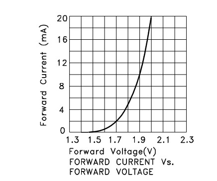
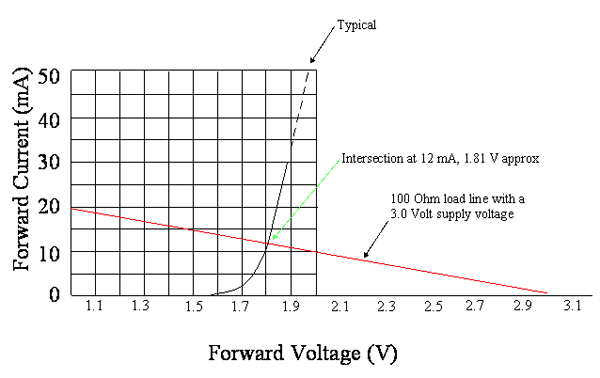
BUT the Vf in the data sheet was at 20 mA. As current drops Vf will fall "somewhat". Here's the characteristics of the chosen LED from its datasheet.

We can see that Vf is about 1.7V at 2 mA and about 1.78V at 4 mA so the assumed value of 1.8V is good enough for our purposes.
- E12 - most common resistor series with 5% accuracy - 12 resistors per decade.
Preferred number series - search for E12, and then read the rest as well :-)
E12 specific - values and colour codes - more focused but less useful overall


