1
\$\begingroup\$

I have a 12V Tachometer Pulse Signal From an ignition unit(From the data sheet)...I would like to feed this pulse into a micro-controller to output the speed to a LCD display. I don't have a scope to put on the 12v signal, but I did put it on a multimeter and the frequency matches what I was expecting. Albeit, the signal is a bit jumpy.

What's the right way to connect this pulse into MCU? Optoisolator?

Is this a safe way to connect the 12v Pulse into the MCU? Should I use a voltage divider on the pulse?
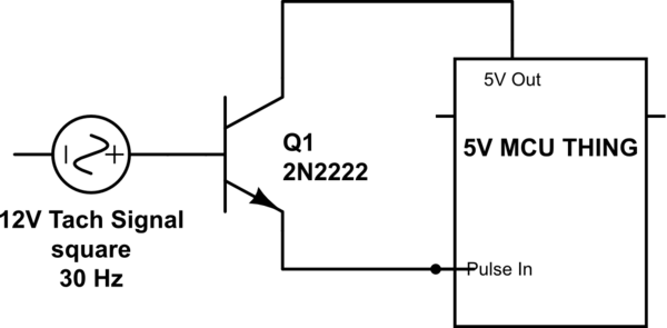
schematic

simulate this circuit – Schematic created using CircuitLab

\$\endgroup\$

2 Answers 2

3
\$\begingroup\$

You cannot use the NPN in this fashion. When the base of Q1 is greater than the collector voltage by 1 diode, you will forward bias the base-collector junction. This is not a normal operating point for the transistor and depending upon the impedance of the 5V node could cause excessive current flow through this path and damage Q1.

If all you want to do is feed a 12V signal into a 5V MCU pin, a simple resistive voltage divider should suffice.

\$\endgroup\$
2
  • \$\begingroup\$ I'm also concerned about isolating the 12v signal so there's no chance of damage to the MCU. I will do some testing also \$\endgroup\$
    – GisMofx
    Commented Jul 6, 2015 at 21:25
  • \$\begingroup\$ You could use an opto-isolator to step down the voltage and isolate the signal if that is of concern. \$\endgroup\$
    – M D
    Commented Jul 6, 2015 at 21:26
3
\$\begingroup\$

Something like this should work well, at least up to a couple kHz. It uses a Fairchild FOD817 optoisolator.

schematic

simulate this circuit – Schematic created using CircuitLab

\$\endgroup\$
9
  • \$\begingroup\$ Thanks! I will try this and report back. What's the purpose of the Diodes and Resistors? \$\endgroup\$
    – GisMofx
    Commented Jul 7, 2015 at 2:59
  • \$\begingroup\$ Two resistors in case either gets shorted to ground there's still one resistor, diode to prevent reverse connection or negative transient from damaging the LED. If you feel like living dangerously a single 1K and no diode. \$\endgroup\$ Commented Jul 7, 2015 at 4:08
  • 1
    \$\begingroup\$ Gotcha..Parts Ordered...Would 330ohm for R2 and R3 work? \$\endgroup\$
    – GisMofx
    Commented Jul 7, 2015 at 15:16
  • \$\begingroup\$ @GisMofx Sure, that will yield about 16mA at 12V, which is still reasonable. \$\endgroup\$ Commented Jul 7, 2015 at 15:17
  • \$\begingroup\$ Hi Spehro, I tested this circuit, it works, but I get a little more noise on the output signal...Can you make any suggestions to clean the output signal back up? I tried a 100nF cap across pins 3 and 4 of the FOD817 and it helped a little, but still not great. \$\endgroup\$
    – GisMofx
    Commented Jul 23, 2015 at 15:54

Your Answer

By clicking “Post Your Answer”, you agree to our terms of service and acknowledge you have read our privacy policy.

Not the answer you're looking for? Browse other questions tagged or ask your own question.