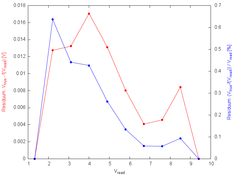
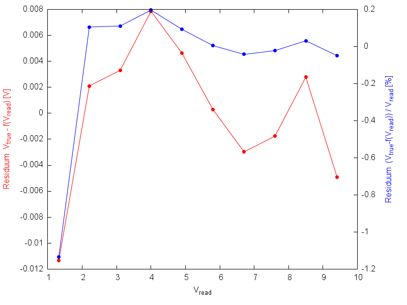
I'm designing a voltmeter and current measurement system that forms part of a electronic load. Lets tackle the volt meter first.
I'm using a 16-BIT ADC (AD7708) and want to measure the following voltages see below, the ADC is pretty neat for DC applications and is used in the BK8500 instrument.
Here us what I want to achieve.
0.1V to 25V ( A resolution of 1mV with an accuracy of 0.05%) 0.1V to 120Vmax ( A resolution of 10mV with an accuracy of 0.05%)
I've written the painful driver code (based on the datasheet) that does all initialization start-up routines like zero calibration, internal DSP filtering, ADC gain and single ended operation mode. So far so good, it works, as I can measure good accuracy against my Fluke 87V from 1mV to 2.5V (ADC FSD)
Note: The ADC is using a external precession 2.5 Volt Reference (ADR421) and powered using a low noise power supply (DP832).
http://www.analog.com/media/en/technical-documentation/data-sheets/ADR420_421_423_425.pdf
Question 1
I'm confused as to how to design a scaling resistor front-end with a suitable gain amplifier for the 25V range and 120V range. so far my attempts are failing, the resistor divider ratio I used to scale for 25V are 100uV per 1mV for R1 = 18K and R2 = 2K (Where R1 and R2 presents a simple resistor divider) Are there any good examples I can use as a guide for this sort of design?
Question 2
How does a design incorporate calibration coefficients, is there a standard design for this? How much ADC coefficients are required to influence a measurement? Is it across the entire measurement range or only for low resolution readings.?


