0
\$\begingroup\$

Having some trouble with transistor logic.

I have an existing circuit with a 3.3V rail and signal rail that is pulled to 0V when asserted, i.e. active low. I ultimately need to control four 12V LED clusters, which draw 125mA each. From hereon I shall refer to 'four 12V LED clusters' as a single LED for simplicity. I can use PNP transistor to power a 12V LED, However I would like a second LED that is the inverse of the first.

I tried to add NPN, with the base on the signal and a pullup resistor on the base to the 3.3v rail but this causes the PNP to be always on as current can flow from the PNP base through the NPN base to the 0V rail. A diode would stop the flow for the NPN.

After reading CharlieHanson comment got further on but I need the LEDs to be ON or OFF not reduced.

see simulation here

EDIT: To reiterate, Switch 1 does not exist. It's an output of another board that is either high impedence (actually disconnected) or 0V.

\$\endgroup\$
5
  • \$\begingroup\$ How can you power a 12v LED from a 3V3 rail? Also, get rid of the link to the crappy falstad circuit and use the editor to draw a proper one (or upload a diagram) - this time make sure you draw it properly without the battery shorted. \$\endgroup\$
    – Andy aka
    Commented Jul 22, 2015 at 8:38
  • \$\begingroup\$ The diagram i linked to show a 12v rail as well, there is no battery shorted in the diagram, there is however a battery that is not connected, that is different from sorting. that was left to show I have a 3.3v rail available if needed for the solution. \$\endgroup\$
    – Arthur
    Commented Jul 22, 2015 at 8:52
  • \$\begingroup\$ Just use a second NPN and connect its base via a resistor to the collector of first NPN. You should also use another resistor on the base of first NPN..... Just look thru some tutorials of "transistor as a switch" or "transistor to switch led" or something like that... Google should be your first option. \$\endgroup\$
    – Golaž
    Commented Jul 22, 2015 at 10:47
  • \$\begingroup\$ Can you check this? take a NMOSFET. Connect source to ground, Gate to the Emitter of PNP, Drain to the negative of D2, Positive of the D2 to the supply(12 V). A 100 kohm resistor between Gate and ground optionally... \$\endgroup\$
    – User323693
    Commented Jul 22, 2015 at 10:51
  • \$\begingroup\$ The 2N3906 collector current maximum is 200mA (0.2A). What current is your LED clusters rated at? If it's near or over 200mA, this transistor will get too hot and fail. \$\endgroup\$
    – rdtsc
    Commented Jul 22, 2015 at 12:39

1 Answer 1

2
\$\begingroup\$

It's not clear why you have chosen a PNP transistor to begin with - I assume it's because you had to start with something. Throw it in the bin; get some MOSFETs, Darlington transistors or beefy NPN transistors (in order of current-conducting capacity, highest to lowest, generally speaking).

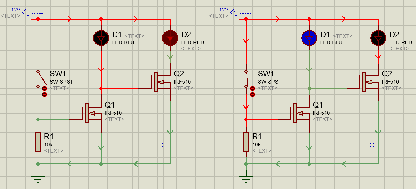
The following diagram uses IRF510 MOSFETs, which are standard off-the-shelf types and are sold on all manner of hobby electronics sites in one form or another - maybe IRF540 or 530 instead. It can handle currents of 4A or more (read the datasheet!) and requires very little in the way of external components, as you can see:

enter image description here

You don't need the 3.3V rail; it's of no use. If you can provide some specs for the 12V LED cluster (we accept datasheets or cold, hard numbers) then somebody can suggest a suitable device to drive it if you have trouble sourcing certain components.

EDIT:

In the Falstad circuit you had the forward voltage of the LEDs too low (11V). That simulator is very basic at best, and so was only dropping 11V across the diode leaving 1V at the gate of the second MOSFET. The emmended can be viewed here.

\$\endgroup\$
5
  • \$\begingroup\$ Thanks Charlie, that what i want, Except that my input signal line is either disconnected or 0v, (I was trying to symbolise that with sw1), The Led's that im using are G4 24SMD 1.5W DC12V, 125mA * 4 (because i want to be able to drive 4 in parallel) = 500ma \$\endgroup\$
    – Arthur
    Commented Jul 22, 2015 at 13:20
  • \$\begingroup\$ Then swap R1 and SW1 - now D1 will be on with the switch open, and D2 with the switch closed. \$\endgroup\$ Commented Jul 22, 2015 at 13:24
  • \$\begingroup\$ The IRF710 comes out as the cheapest non-surface-mount, >600mA MOSFET on Farnell's website. You may find it cheaper elsewhere, or an even cheaper alternative. So long as the Ids (drain-source current) is greater than the maximum draw plus some breathing room then you can't go too wrong. \$\endgroup\$ Commented Jul 22, 2015 at 13:40
  • \$\begingroup\$ is this simulator wroung then it shows D2 on a bit when sw1 is open \$\endgroup\$
    – Arthur
    Commented Jul 22, 2015 at 14:09
  • \$\begingroup\$ See my edit regarding your simulation. \$\endgroup\$ Commented Jul 22, 2015 at 14:24

Your Answer

By clicking “Post Your Answer”, you agree to our terms of service and acknowledge you have read our privacy policy.

Not the answer you're looking for? Browse other questions tagged or ask your own question.