Overflow enthusiasts!
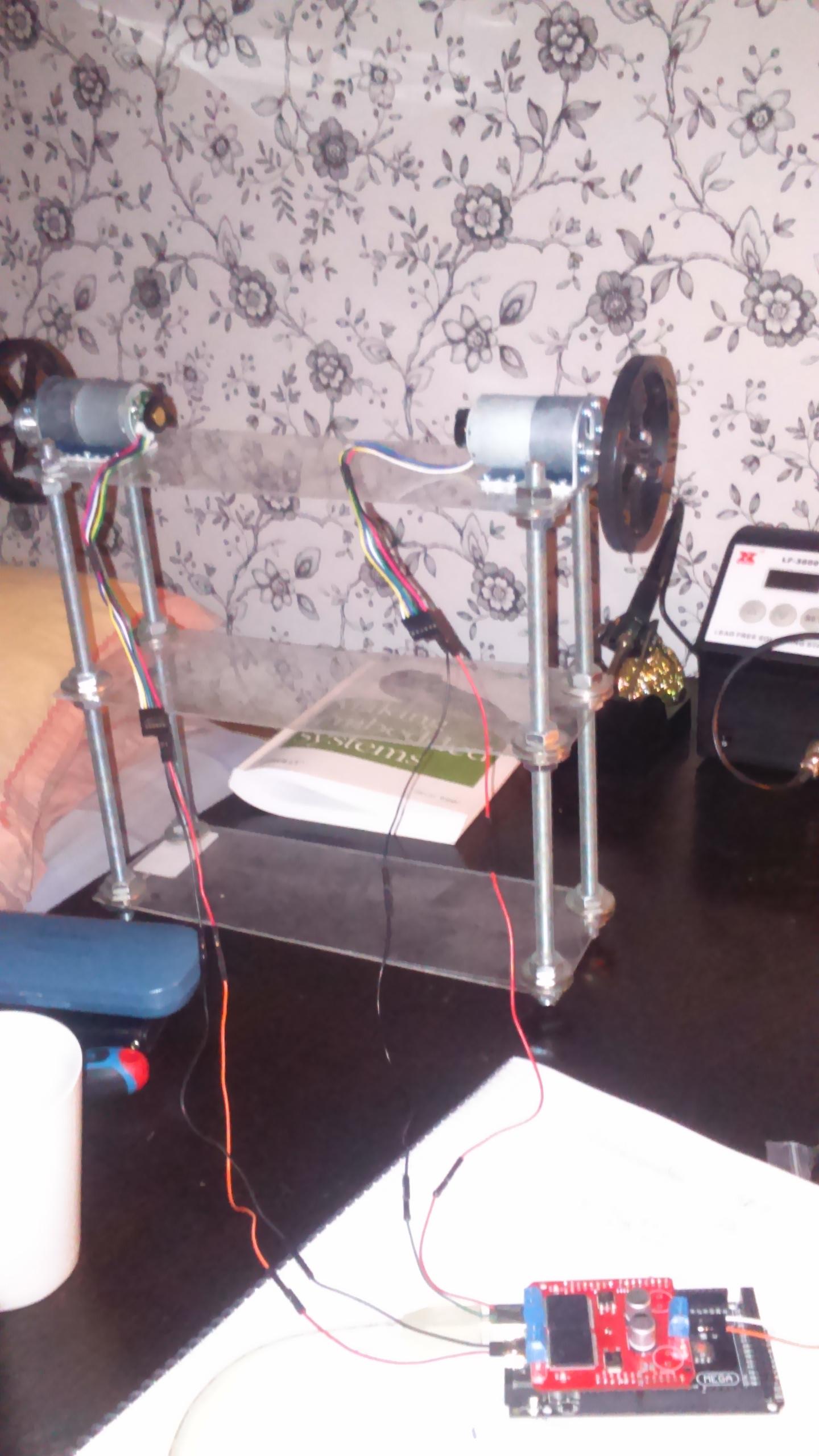
I am trying to build a balancing robot with two wheels, using the polulu gear motor as mentioned above. In order to have a strong motor driver,the monster moto shield is used in this project. Here is the components and datasheets which is used.
Components
Lipo batteries Arduino saint smart 2x Pololu 12V, 29:1 Gear Motor w/Encoder Monster moto shield
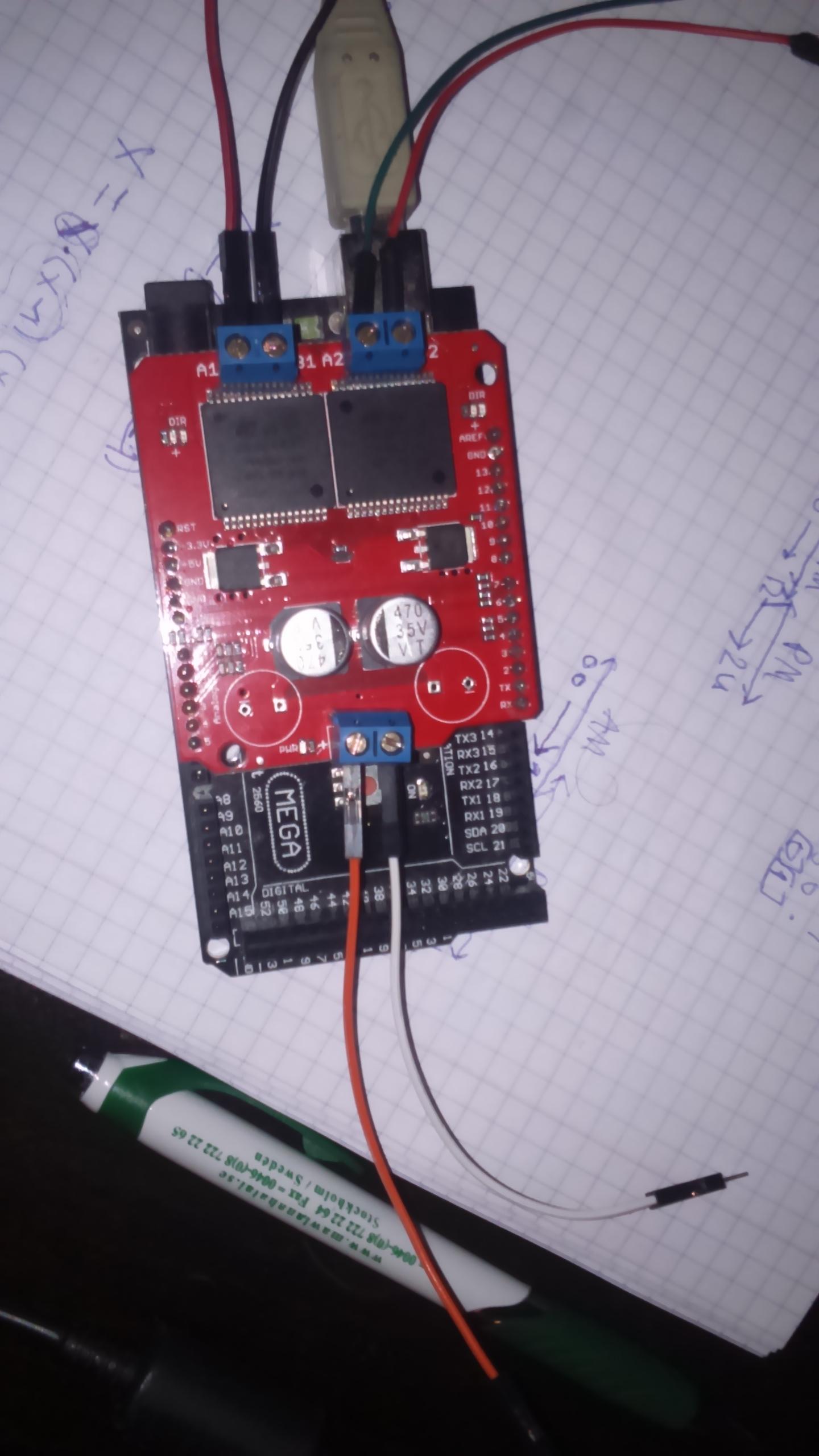
Now, back to the issue.. Well, the first problem I encountered was my motor driver. It keeps getting hot after a while, whenever I use it ( I run 2 motors through 1 driver). And the most frustrating part is that the motors can stop for a while, and then restart again ( suspect a hardware reset here). Is there any way this can be solved?, I have checked the datasheet for the monster moto driver but can't understand whether the components are already on the PCB boad or I manually have to add new components like resistors, capacitors and etc. Would be glad if you guys directed me on this issue.
Secondly, The other problem I have is that the motors are going fast CW and slow CCW whenever I reverse direction. I have also seen other ppl getting the same problem as I do and wonder why this happen.
Should I add external components ? Then which components should I use in order to subdue this problem?
Here are some pictures in order to clarify the problem. Mostly using cables to connect inputs and etc. I would be glad if you wonder something and want me to post more information.
pictures:
Code
/*  MonsterMoto Shield Example Sketch
  date: 5/24/11
  code by: Jim Lindblom
  hardware by: Nate Bernstein[![enter image description here][1]][1]
  SparkFun Electronics
 This is really simple example code to get you some basic
 functionality with the MonsterMoto Shield. The MonsterMote uses
 two VNH2SP30 high-current full-bridge motor drivers.

 Use the motorGo(uint8_t motor, uint8_t direct, uint8_t pwm)
 function to get motors going in either CW, CCW, BRAKE[![enter image description here][1]][1]VCC, or
 BRAKEGND. Use motorOff(int motor) to turn a specific motor off.

 The motor variable in each function should be either a 0 or a 1.
 pwm in the motorGo function should be a value between 0 and 255.

This code is beerware; if you see me (or any other SparkFun employee) at the
local, and you've found our code helpful, please buy us a round!
Distributed as-is; no warranty is given.
 */
#define BRAKEVCC 0
#define CW   1
#define CCW  2
#define BRAKEGND 3
#define CS_THRESHOLD 100

/*  VNH2SP30 pin definitions
 xxx[0] controls '1' outputs
 xxx[1] controls '2' outputs */
int inApin[2] = {7, 4};  // INA: Clockwise input
int inBpin[2] = {8, 9}; // INB: Counter-clockwise input
int pwmpin[2] = {5, 6}; // PWM input
int cspin[2] = {2, 3}; // CS: Current sense ANALOG input
int enpin[2] = {0, 1}; // EN: Status of switches output (Analog pin)

int statpin = 13;

void setup()
{
  Serial.begin(9600);

  pinMode(statpin, OUTPUT);

  // Initialize digital pins as outputs
  for (int i=0; i<2; i++)
  {
    pinMode(inApin[i], OUTPUT);
    pinMode(inBpin[i], OUTPUT);
    pinMode(pwmpin[i], OUTPUT);
  }
  // Initialize braked
  for (int i=0; i<2; i++)
  {
    digitalWrite(inApin[i], LOW);
    digitalWrite(inBpin[i], LOW);
  }
  // motorGo(0, CW, 1022e3);
  // motorGo(1, CCW, 1023);
}

void loop()
{
  motorGo(0, CW, 1023);
  motorGo(1, CW, 1023);
  delay(500);
  motorGo(0, CCW, 1023);
  motorGo(1, CCW, 1023);
  delay(50);
  if ((analogRead(cspin[0]) < CS_THRESHOLD) && (analogRead(cspin[1]) < CS_THRESHOLD))
    digitalWrite(statpin, HIGH);
}

void motorOff(int motor)
{
  // Initialize braked
  for (int i=0; i<2; i++)
  {
    digitalWrite(inApin[i], LOW);
    digitalWrite(inBpin[i], LOW);
  }
  analogWrite(pwmpin[motor], 0);
}

/* motorGo() will set a motor going in a specific direction
 the motor will continue going in that direction, at that speed
 until told to do otherwise.

 motor: this should be either 0 or 1, will selet which of the two
 motors to be controlled

 direct: Should be between 0 and 3, with the following result
 0: Brake to VCC
 1: Clockwise
 2: CounterClockwise
 3: Brake to GND

 pwm: should be a value between ? and 1023, higher the number, the faster
 it'll go
 */
void motorGo(uint8_t motor, uint8_t direct, uint8_t pwm)
{
  if (motor <= 1)
  {
    if (direct <=4)
    {
      // Set inA[motor]
      if (direct <=1)
        digitalWrite(inApin[motor], HIGH);
      else
        digitalWrite(inApin[motor], LOW);

      // Set inB[motor]
      if ((direct==0)||(direct==2))
        digitalWrite(inBpin[motor], HIGH);
      else
        digitalWrite(inBpin[motor], LOW);

      analogWrite(pwmpin[motor], pwm);
    }
  }
}
regards, Volkan


