7
\$\begingroup\$

I have two 12v lead acid batteries on my boat. One at the front for the trolling motor (~80 AH) and 2 smaller batteries in parallel at the rear for electronics (~30-35 AH combined).

I want to put a solar panel on my garage, so I can hook the batteries up when I get back from the lake to recharge them and to keep them maintained. I only need a 30 or 50 watt panel to charge both battery banks, since I never use full capacity and usually have at least couple days between trips. Instead of buying 2 smaller panels, one for each battery bank, I was thinking about hooking up 2 charge controllers to the same solar panel.

The solar panel disconnect switch is required because the batteries should be connected to the charge controllers before the solar panel is connected. On my boat, I would add DC plugs for both batteries to connect the charge controllers.

I think this will work fine, but I have done a lot of searching and could not find any information about connecting multiple charge controllers to the same solar panel. I am aware they make dual battery charge controllers, but they don't look any better than the $10 units you can find on Amazon and they are more than double the price.
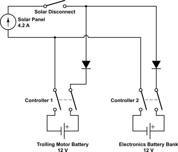
schematic

simulate this circuit – Schematic created using CircuitLab

\$\endgroup\$
8
  • \$\begingroup\$ Might work. Cheap charge controllers are a bang bang MOSFET switch, so either the battery is straight on the solar cell, or not. Once the battery is full, the switch will be mostly off, so the other charge controller can use the cell. Danger might be shorting two batteries together, but you could check for diodes or add them (before the controllers)... \$\endgroup\$
    – tomnexus
    Commented Jul 27, 2015 at 22:18
  • \$\begingroup\$ This makes sense. If the charge controllers have diodes built in, then the extra diodes wouldn't be necessary, but I'd still want them so the batteries don't drain at night. Without diodes, both battery banks would essentially be connected in parallel with the solar panel when both controller switches are closed (connected). \$\endgroup\$
    – AndrewR
    Commented Jul 27, 2015 at 22:52
  • \$\begingroup\$ Mis-typed... If the charge controllers do have diodes, then extras are not needed. If they don't have diodes, I'd still want to add them regardless of the batteries connecting in parallel to the solar panel. \$\endgroup\$
    – AndrewR
    Commented Jul 27, 2015 at 23:02
  • \$\begingroup\$ Yes, you might need to add two diodes to prevent the batteries from being connected in parallel. But don't put a diode between the controller and the battery, as it won't be able to sense the battery voltage correctly. \$\endgroup\$
    – tomnexus
    Commented Jul 28, 2015 at 4:54
  • \$\begingroup\$ On your diagram, replace the solar cell battery with a current source, and replace the charge controllers with simple switches that connect the battery, and you have a more reasonable model. Only question is, what does the controller do when the solar voltage collapses to ~14V (when the other one shorts the panel to the battery). It might panic and not charge. It's worth asking the supplier, I'm sure they've had that question before. \$\endgroup\$
    – tomnexus
    Commented Jul 28, 2015 at 4:58

2 Answers 2

3
\$\begingroup\$

Should work. Cheap charge controllers are a bang bang MOSFET switch, so either the battery is straight on the solar cell, or not. MPPT controllers have a switch mode buck converter; two of them on one panel will get very confused.

Once the battery is full, the charge controller switch will be mostly off, so the other charge controller can use the solar cell.

The danger might be that if both batteries are low, both controllers will come on together, shorting two batteries together and damaging the controllers. You could check for diodes or add them. They must go before the controllers, not between the controller and the battery, as it needs to sense the battery voltage.

The open questions are 1) are there already diodes in the charge controller, and 2) what does the controller do when the solar voltage collapses to ~14V (when the other one shorts the panel to the battery). It might panic and not charge.
It's worth asking the supplier about both of these, I'm sure they've had these questions before

\$\endgroup\$
1
  • 1
    \$\begingroup\$ 1) Depends on the charge controller. Apparently some do and some cheaper ones don't. 2) It should work. From what I've found, charge controllers don't care about the input voltage (as long as it's not too high) and whether the switch is open or not depends on the battery. \$\endgroup\$
    – AndrewR
    Commented Jul 29, 2015 at 18:43
0
\$\begingroup\$

I have a similar question. Theoretically, you can have both charge controllers on the same pv array solar panel. I understand that it will work fine if the output of each controller is going to a different battery or battery bank. However, if the load voltage drop of both controllers brings the voltage below its minimum input voltage, then they would not have any output voltage. On the other hand if the input is acceptable, both controllers will use the available current to produce a useful charge, which would be divided between the two controllers. If it does not work nothing will happen; the controller will simply not work, as if the voltage were too low when there is little light.

Again this a theory. I have two parallel controllers working on the same battery bank, and they work fine. Nevertheless, each controller uses different pv array sets. If I put all the panels together in one set (array) and tried to charge the same battery bank using the two controllers on the same array, it could present a conflict when one goes to float charge and the other is in bulk still trying to charge the batteries. This could happen because the settings on the two are not exactly the same. This conflict will not take place if the controllers' outputs are going to different battery banks. Perhaps the answer is not straight forward, but there is an answer if you reflect a little bit.

My answer is: Yes, you can have two controllers on a one set of panels (array). Each controller is independent, and the outputs will not be parallel unless you put them that way. If you connect the output of each controller on two separate battery banks, each controller will charge the bank that is connected to its output using whatever power is available depending on the need (state of charge) the battery bank has. When a bank is full, the total power of the panels will be available for the other bank, while the fully charged one would remains off. If both are charging, the power available will divide between the two banks. Basically, it will be like connecting two pieces of equipment to the same power source.

I hope this will be of help to you.

\$\endgroup\$
2
  • 1
    \$\begingroup\$ I'm not really sure how this is supposed to answer OP's question, as he is not asking about using two controllers on a single bank? Making up a new situation that won't work, and saying that OP's situation doesn't have that problem, is not an answer to his question, and frankly completely unrelated. \$\endgroup\$
    – I. Wolfe
    Commented Jan 11, 2017 at 22:50
  • \$\begingroup\$ The information is based on experience and real situation on my solar system; maybe I should have gone straight to the point, but if the answer was not clear because of the distractor, I hope have given a direct answer now. Have a great day, Marcelino \$\endgroup\$
    – user143783
    Commented Mar 29, 2017 at 21:24

Not the answer you're looking for? Browse other questions tagged or ask your own question.