1
\$\begingroup\$

Say I have two 500F ultra capacitors, connected in parallel, charged at 15V.

These are the capacitors BMOD0500 P016 B01.

Then say I connect the capacitors (via an inverter) to a 230V light bulb that draws a constant 280W of power (the inverter disconnects at 10V).

What equation would I use to calculate the amount of time that the circuit would remain active?

Please ignore the efficiency of the inverter, I'll take that into account later.

\$\endgroup\$
4
  • \$\begingroup\$ It won't be a decaying exponential. Because it is a constant power load, the capacitor voltage will fall away initially at a rate of x then this rate will increase as the voltage drops towards 10V. \$\endgroup\$
    – Andy aka
    Commented Jul 29, 2015 at 10:38
  • \$\begingroup\$ thanks andy (have amended the question). Do you know the formula and hence the amount of time the circuit will remain active? \$\endgroup\$ Commented Jul 29, 2015 at 10:53
  • \$\begingroup\$ You'll have to account for the increasing current as the voltage reduces. You'll also have to account for the ESR of your capacitor - it would be useful to specify that in the question, or link to the capacitor datasheet if you're not sure about it. \$\endgroup\$
    – user16324
    Commented Jul 29, 2015 at 11:13
  • \$\begingroup\$ Initial discharge at 18.7A (15V, 0.8R load) rising to 28A (10V, 0.34R load) - that's gonna need a big switch \$\endgroup\$ Commented Jul 29, 2015 at 11:34

2 Answers 2

5
\$\begingroup\$

If we model the setup with a capacitor in parallel with the load, and let \$i\$ be the current into the load and \$v\$ the voltage across the two, the circuit equations are:

$$ \left\{ \begin{aligned} -i &= C \dfrac {dv} {dt} \\[1 em] v i &= P \end{aligned} \right. \qquad \Leftrightarrow \qquad \left\{ \begin{aligned} -i &= C \dfrac {dv} {dt} \\[1 em] i &= \dfrac P v \end{aligned} \right. $$

Where P is the constant power level. Putting the two together will give you this differential equation:

$$ C \dfrac {dv} {dt} = - \dfrac P v \qquad \Leftrightarrow \qquad v dv = - \dfrac P C dt \qquad \Leftrightarrow \qquad 2 v dv = -2 \dfrac P C dt $$

If we integrate starting at instant 0 where we assume a voltage \$v_0\$ is across the cap, we get:

$$ \int_{v_0}^{v} {2 v dv} = \int_0^t {-2 \dfrac P C dt} \qquad \Leftrightarrow \qquad v^2 - v_0^2 = -2 \dfrac P C t $$

From which you can readily get a formula for the voltage and the time:

$$ t = \dfrac {C}{2 P} (v_0^2 - v^2) \qquad v = \sqrt{v_0^2 - \dfrac{2P}{C} t} $$

If we want to take into account the ESR or other circuit elements the equation becomes nastier to solve, but for an initial guess it should be good enough.

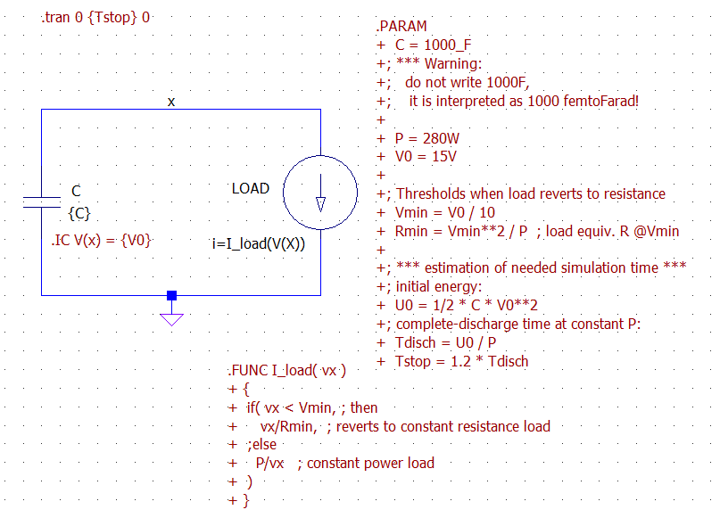
Here is an LTspice simulation for the system. Notice that the load has been modeled by a behavioral current source that behaves as a constant power load only until its voltage reaches Vmin, then reverts to a constant resistance behavior. This is needed to avoid numerical instability in the simulation, since a true constant power source is not a physical device (with 0 volts draws infinite amperes).
enter image description here

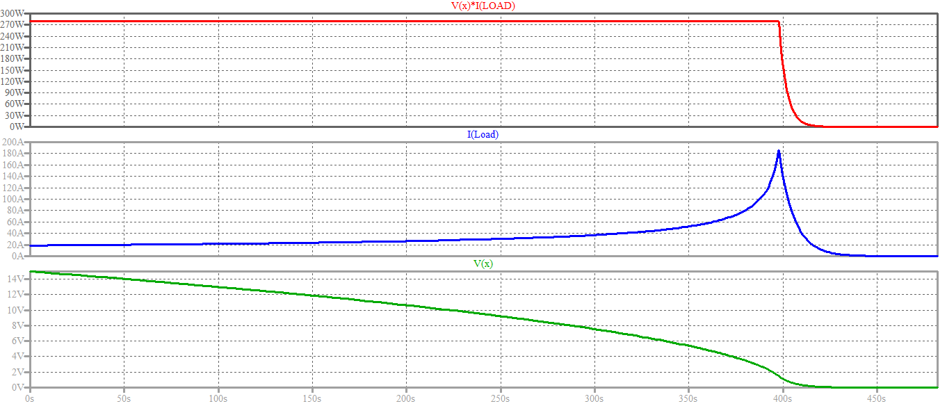
And here are the results. You can notice the confirmation of the time-reversed square-root shape of the voltage Vx predicted theoretically above. The shapes of the signals change to the usual exponentially-decaying voltage and current when the load switches to constant resistance mode.
enter image description here

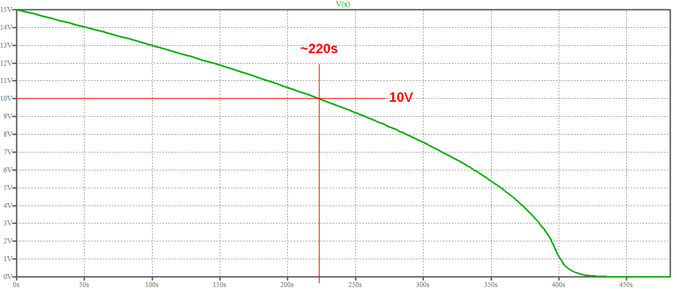
Here is a zoomed graph of the voltage, which shows the time value you are after:
enter image description here

Which is coherent with the value computed with the formula above:

$$ t_{shutdown} = t(v)\bigg|_{v=10V} = \dfrac {C}{2 P} (v_0^2 - v^2)\bigg|_{v=10V} = \dfrac {1000F}{2 \times 280W} \left[(15V)^2 - (10V)^2\right] = 223.2 s $$

\$\endgroup\$
1
  • 1
    \$\begingroup\$ Hi Lozenzo, what can I say! fantastic and extremely comprehensive answer. Hats off to you sir. \$\endgroup\$ Commented Jul 29, 2015 at 19:24
3
\$\begingroup\$

A theoretical answer as for a homework problem would be to take the energy in the capacitor at the start and the energy in the capacitor when the device stops working (10V, presumably) and subtract the two.

\$\Delta\$U = \$(\frac{CV_i^2}{2}\$ - \$\frac{CV_f^2}{2})\$

Since you know the rate of energy consumption (280J/s) you can calculate the run time easily.

\$\endgroup\$
2
  • \$\begingroup\$ That looks too easy to be possible but if you have no interest in the waveforms then it should be plenty precise if the ESR can be neglected. Does it tally with the other answer? \$\endgroup\$
    – KalleMP
    Commented Jul 29, 2015 at 22:30
  • 1
    \$\begingroup\$ Yup, exactly the same as Lorenzo's answer. 223.21 s. \$\endgroup\$ Commented Jul 29, 2015 at 23:03

Your Answer

By clicking “Post Your Answer”, you agree to our terms of service and acknowledge you have read our privacy policy.

Not the answer you're looking for? Browse other questions tagged or ask your own question.