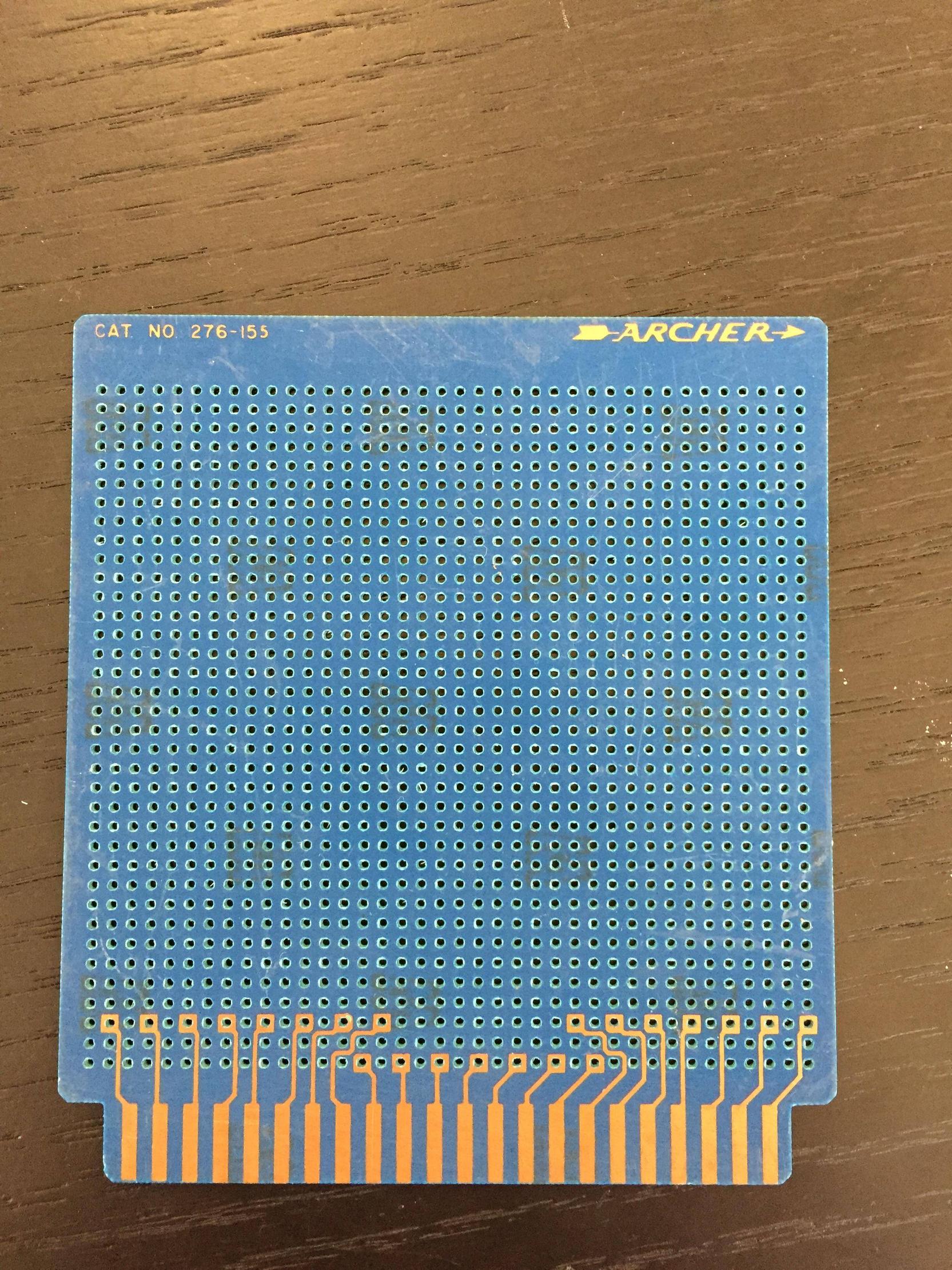
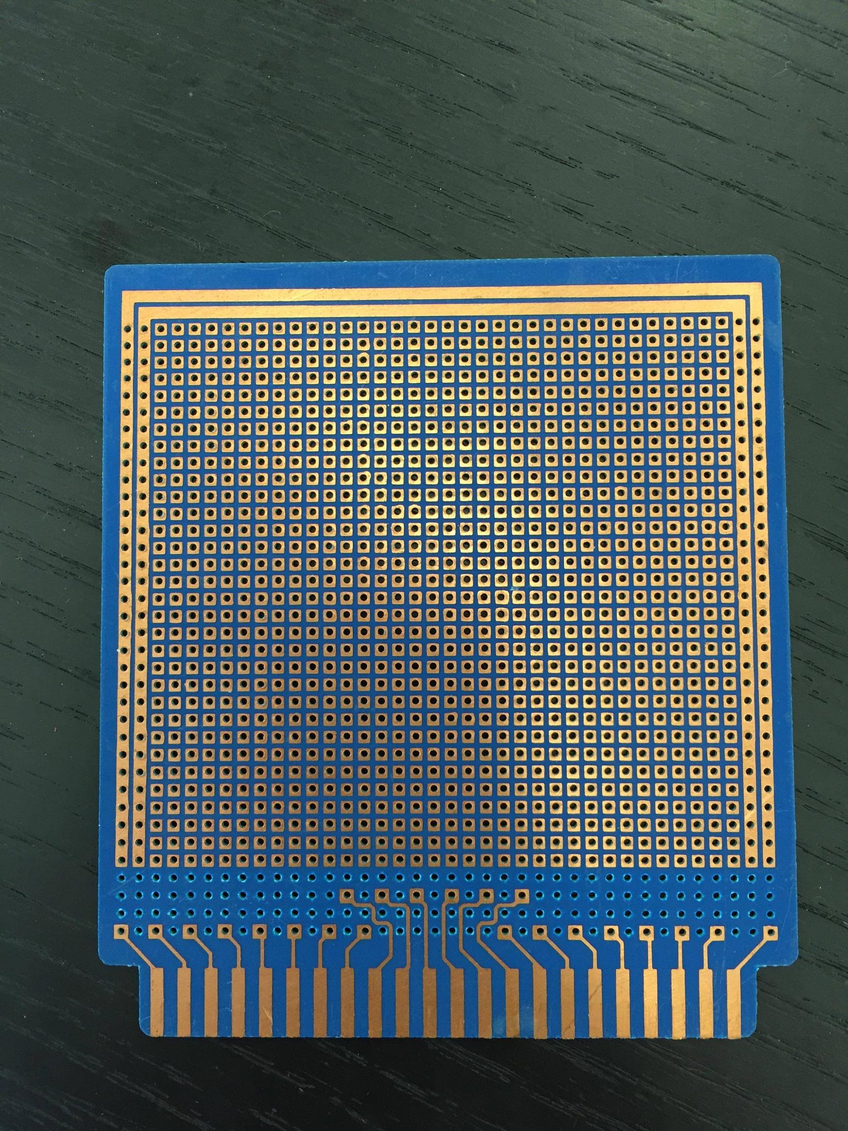
A friend of mine had this lying on a shelf- he had found it while cleaning out his basement. Any idea what it is meant to slot into, or its purpose in general?
2 Answers
Googling the part number (thanks for including it in a nice clear photograph!) produces:
So it has no specific purpose, although the 44-way edge connector will fit in your VIC-20 expansion port.
-
\$\begingroup\$ Actually, that's a 0.156 pitch connector (you can verify by measuring the using 0.1 hole spacing), and the VIC-20 had a 0.196 spacing, so it won't work for that purpose. \$\endgroup\$ Commented Jul 30, 2015 at 13:58
-
\$\begingroup\$ Hadn't thought of pitch incompatibilities. It looks vaguely Eurocard but Eurocard has DIN connectors. Is there any standard it would fit? \$\endgroup\$– pjc50Commented Jul 30, 2015 at 14:41
-
\$\begingroup\$ Not that I know of. It's just the standard .156 connector that was very popular through the 70s and 80s before higher-density connectors became accepted. You can still buy them, though, so they're clearly still in use in industry. For cheap connections, PC fingers really can't be beat, although reliability is a problem. \$\endgroup\$ Commented Jul 30, 2015 at 14:47
-
\$\begingroup\$ Would this connector work? (Just wondering, I don't intend to implement this anywhere) jammaboards.com/store/… \$\endgroup\$– MacCommented Jul 30, 2015 at 18:59
We used to call them Vero boards because the Vero company was a major manufacturer. They were generally used for analog circuits. There were metal pins that fit into the holes. You soldered one end of the pin to the landing. The other end was used to mount components. The board required point to point wiring. There was also a mating edge connector and a rack to hold several boards so a fairly complex system could be prototyped.


