2
\$\begingroup\$

I'm trying to make a current buffer for high currents, using an LM324 and BUZ70. This is the circuit:
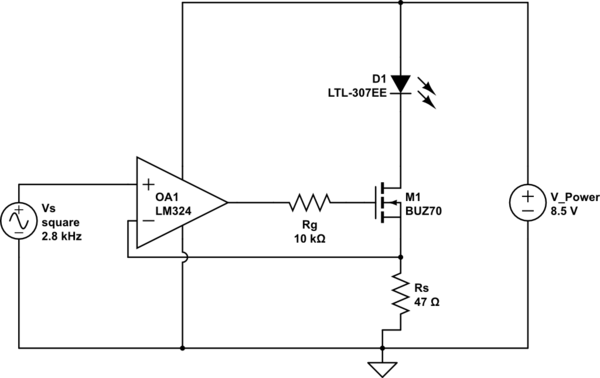
schematic

simulate this circuit – Schematic created using CircuitLab

I've noticed that this circuit starts to have a little oscillation (at least 100 times more the Vs frequency) overlapped to the gate voltage if a gate resistance of around 10Kohm is used. Removing this resistance, will remove the oscillation.

Just for completeness, there is also an evident miller effect, in which the initial ramp before the miller plateau is enlarged if a gate resistor of 10K is used, and this should be coherent.

The oscillation disappears also if the led is fed at 5V.

If Vs is a DC voltage, the oscillation takes place too, showing that it is NOT a transient ringing.

It is a breadboarded circuit, but in any case, I think that I have a very little phase margin, but this circuits should have a very large bandwidth.

Any opinion?

edit: when the LED is turned on, fraction of this oscillation is present in V_Power. I may solve this by putting a cap here and there and not using an high gate resistance, but I'd prefer to understand why, if it is possible.

edit1: as stated in comments, I need a compesation if the source resistance is less than 50 ohm. I don't understand, because modelling the system using this circuit:
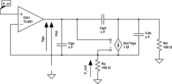
schematic

simulate this circuit

I obtain

$$V_{out}= \frac{R_s G_m}{1+R_s G_m} \frac{1-\frac{s}{z_1}}{1-\frac{s}{p_1}} V_{oa} = k V_{oa}$$

with $$z_{1} = -\frac{g_m}{C_{gs}}$$ $$p_{1} = -\frac{1}{C_{gs}\frac{R_s}{1+g_m R_s}}$$

and this does not affect the stability of the opamp, which is an LM324 with a limited band. The Cgs used is the provided Ciss, the gm = 2 (because of the limited current used now, see datasheet of BUZ70).

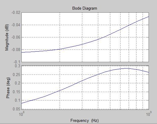
In fact, this MOSFET stage have the Vout/Voa with a bode of:

Matlab simulation

Therefore I can consider the system with the OPAMP asa voltage follower. Why I need to add compensation with low Rs values?

\$\endgroup\$
2
  • \$\begingroup\$ Isn't the circuit astable when the square wave is high? What is it's amplitude? \$\endgroup\$
    – Eugene Sh.
    Commented Aug 5, 2015 at 15:35
  • \$\begingroup\$ Hi, I didn't see your comment. I know now it's old, but... what do you mean by astable? \$\endgroup\$
    – thexeno
    Commented Apr 14, 2016 at 20:07

2 Answers 2

5
\$\begingroup\$

The gate resistor isn't helping anything (that I can see) so get rid of it!

The circuit should be reasonably stable (without the 10K resistor) so long as your MOSFET source resistor doesn't get too much lower than it is. If you need lower than about 50 ohms then you'll need to add compensation.

Be sure to check stability with a relatively small square wave perturbation in command voltage, with both voltages in the linear range (eg. 20mA to 22mA).

You don't indicate what kind of bandwidth you are looking for, but usually LM324 and 'very large bandwidth' don't go together. The 10K and gate capacitance form another pole at about 40kHz and, as you've observed, there is Miller capacitance to the extent the drain voltage (V_power - LED forward voltage) changes with changing current.

\$\endgroup\$
8
  • \$\begingroup\$ See the EDIT1. PS: I made this job for a personal challenge. \$\endgroup\$
    – thexeno
    Commented Aug 18, 2015 at 12:45
  • \$\begingroup\$ Thanks, I have 2 questions and 1 observation. When you say about the pole at 40kHz, you seem to consider the Ciss given. (i) Is that quite affordable? (ii) As a consequence, the gate charge values are used only to devise the minimum current capability to fed the Gate and are NOT used to devise the gate capacitance? Observation: If the pole is at 40kHz, then since the opamp works in voltage follower (see the EDIT1), I've -40dB/dec at 40kHz leading to stability problems, so the oscillation that I saw. Right? \$\endgroup\$
    – thexeno
    Commented Aug 18, 2015 at 12:51
  • \$\begingroup\$ The drain voltage doesn't change 'much' so it's mostly gate capacitance to drain + source. Simulate for a more accurate answer. The op-amp has some output resistance even if you get rid of the 10K resistor- maybe 50-100 ohms. You're still getting 30-50% of the feedback even with 50 ohms. AD has a good app note on compensation- far too much to go into in a comment. \$\endgroup\$ Commented Aug 18, 2015 at 13:11
  • \$\begingroup\$ Removing the MOSFET, using the opamp as a voltage follower with a capacitor of 100nF on its output, provides oscillation. I will search for a compensation method -> probably the MOSFET have a significant cap. Just for a personal excercise, the EDIT1 does make sense? At least the math analysis \$\endgroup\$
    – thexeno
    Commented Aug 18, 2015 at 13:53
  • \$\begingroup\$ The MOSFET is more like XXnF in series with the source resistor. That's a huge difference. Try the math with the output resistance of the op-amp (try 100 ohms) included. \$\endgroup\$ Commented Aug 18, 2015 at 14:07
0
\$\begingroup\$

Seem to be easily solved by loading the output with a 10K ohm resistor (or less, or a bit higher is not important). I'd like to know why... Is it reducing the loop gain improving stability?

\$\endgroup\$

Your Answer

By clicking “Post Your Answer”, you agree to our terms of service and acknowledge you have read our privacy policy.

Not the answer you're looking for? Browse other questions tagged or ask your own question.