0
\$\begingroup\$

I'm trying to better understand the layout below. Which is based on a project called "Kraakdoos" [2] which is a touch based musical instrument. And sources suggest that it uses "‘malformed’ oscillators that were very unstable and highly sensitive for finger connections".

However from what I can tell of the circuit there are no explicit oscillators. Is this correct? It simply seems to be a high gain opamp (inverting configuration?). So my question is where does the oscillation come from?

Also am I correct in understanding that the transistors at the output are a push-pull output stage?

The circuit is our course in some respects intensionally wacky, but I'd like to understand it a little better.

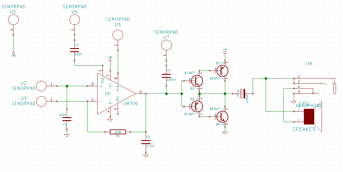
Layout

[2] http://www.eam.se/kraakdoos/

\$\endgroup\$
4
  • \$\begingroup\$ The output is a push-pull stage constructed from two Sziklai Transistor Pairs. electronics-tutorials.ws/transistor/darlington-transistor.html \$\endgroup\$
    – jippie
    Commented Aug 15, 2015 at 22:43
  • \$\begingroup\$ @jippie thanks that's very helpful! I thought they looked a bit like Darlington pairs. \$\endgroup\$
    – new299
    Commented Aug 15, 2015 at 22:44
  • \$\begingroup\$ After reading Dave Tweed's answer (we were writing at the same time), I may have misinterpreted the question. Do you actually want this thing to oscillate? What it the purpose of this circuit? I was assuming audio amplifier. \$\endgroup\$ Commented Aug 15, 2015 at 23:31
  • \$\begingroup\$ @OlinLathrop oh yes, it's designed to oscillate (see my comment on your answer). \$\endgroup\$
    – new299
    Commented Aug 15, 2015 at 23:40

2 Answers 2

3
\$\begingroup\$

It's nominally a noninverting opamp configuration with unity gain, although with a 10M feedback resistor, the feedback is not going to be very effective because of the opamp input's bias current and capacitance.

So yes, the opamp is running essentially open-loop with a feedback path that introduces enough phase shift — along with the phase shifts introduced by touching the various pads — to allow it to oscillate at various frequencies.

The output stage is a push-pull configuration using a complementary Darlington configuration on the top and bottom. However, it isn't biased to eliminate crossover distortion, so it will have a "dead band" in its transfer curve. This probably serves as a gating function that prevents low-level "background" signals from getting through to the output.

\$\endgroup\$
2
  • \$\begingroup\$ Thanks! So it's a kind of phase-shift oscillator? My understanding was that a 180degree phase-shift is required for this, and I'm having trouble seeing how the feedback network could provide this shift. Do you have any references that might help me? \$\endgroup\$
    – new299
    Commented Aug 15, 2015 at 23:20
  • 1
    \$\begingroup\$ The external feedback network provides at most 90 degrees of phase shift. However, remember that the open-loop tranfer function of the opamp itself introduces another 90 degrees -- there's an internal "pole" that causes the gain to drop with increasing frequency (this is why the gain-bandwidth product is constant over a wide range) -- so it isn't difficult to come up with a total of 180 degrees to create an oscillator. The usual design task is to prevent oscillation while accomplishing other goals. \$\endgroup\$
    – Dave Tweed
    Commented Aug 15, 2015 at 23:55
0
\$\begingroup\$

At first glance, this circuit looks like a power amplifier, although there are some problems with the details.

I haven't looked up what exactly all those extra pins do on the opamp, and what a "senorpad" is supposed to be, so I'm just ignoring those. Some issues:

  1. Both inputs are labeled "D". That's just assinine since they both obviously do different things.

  2. The cap on the + input makes little sense without some known impedance driving the top D input. A resistor in series followed by the cap to ground would make a first order low pass filter, which would make some sense.

  3. 1 MΩ feedback is rather high, and working against what? Since this is clearly meant for audio, the top D input should be capacitively coupled, and the bottom D connect to about half the supply voltage.

  4. The cap to ground on the opamp output makes no sense. This will only lead to instability of the amp. If someone observed this circuit oscillating on its own, then this might be the cause.

  5. The feedback does not encompass the power output stage. It will have about a 1.4 V dead zone. With the feedback around it, the opamp can at least in part compensate for this. A fast slew rate opamp would be better, so that it can "jump" across the dead zone quickly to minimize crossover distortion.

  6. With a little extra biasing, much of the dead zone of the output stage could be avoided in the first place.

\$\endgroup\$
4
  • \$\begingroup\$ The schematic got cut off, D should also read "SensorPad". They are just electrical pads which are touched with a finger (like a captouch sensor). The design is from a 1970s musical instrument. I find the design somewhat strange myself which is why I'm trying to understand it better. In particular I'd like to understand what causes it to reliably oscillate. \$\endgroup\$
    – new299
    Commented Aug 15, 2015 at 23:24
  • \$\begingroup\$ @new: Argh! You might have explained up front what this circuit was supposed to do. Much of my answer is invalid now. I'll try to remember to take your questions less seriously in the future. \$\endgroup\$ Commented Aug 15, 2015 at 23:40
  • 4
    \$\begingroup\$ Did you not see "‘malformed’ oscillators that were very unstable and highly sensitive for finger connections" and the citation to the original project? I'd attempted to add some clarification to the question. But your attitude it pretty rude to be honest. \$\endgroup\$
    – new299
    Commented Aug 15, 2015 at 23:45
  • 2
    \$\begingroup\$ @new: I saw those, but it was not clear these were intended affects, not something your amplifier was doing you wished it wasn't. And no, as a general rule I don't follow links except sometimes to datasheets. If the information is important to the question, it should be in the question. Remember that we are all volunteers here that you are asking a favor of. \$\endgroup\$ Commented Aug 16, 2015 at 0:49

Your Answer

By clicking “Post Your Answer”, you agree to our terms of service and acknowledge you have read our privacy policy.

Not the answer you're looking for? Browse other questions tagged or ask your own question.