14
\$\begingroup\$

I would like to make a simple circuit to store or save 1 bit of data. The circuit should be able to remember the state of an LED ( on or off ) even if the supply is disconnected from the circuit. I need it to work like a hard drive, flash memory or SD memory card of cell phones.

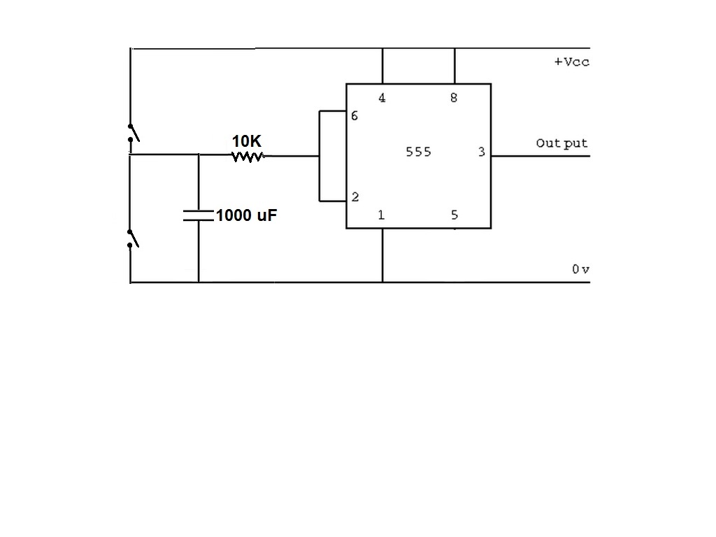
I made a circuit as shown in the picture, The output is an LED in series with 470 ohm resistor. I use two bush buttons to charge or discharge the capacitor so the output LED is on or off.

After disconnecting the supply or turning off electricity, The circuit was able to remember the state of the LED for few minutes.

After 2 or 3 minutes, the capacitor discharged completely and the circuit lost its data.

enter image description here How can I stop the capacitor from discharging ? or how can I slow the rate of discharging so that the circuit lose its data after a week or more ?

In this circuit I uses 555 as an inverter ( not gate ) but I may use any other IC's , My aim is just making a simple permanent memory.

\$\endgroup\$
8
  • 1
    \$\begingroup\$ How averse are you to using a coin cell? There is no way to duplicate a EEPROM/flash/FRAM cell at a macro level. \$\endgroup\$ Commented Aug 31, 2015 at 22:54
  • 9
    \$\begingroup\$ @IgnacioVazquez-Abrams You could use a latching relay... \$\endgroup\$ Commented Aug 31, 2015 at 23:00
  • 2
    \$\begingroup\$ @MichaelGeorge: No, the whole point of a latching relay is that it uses a permanent magnet to preserve its state without the application of external power. You just need a pulse of electricity to change its state. \$\endgroup\$
    – Dave Tweed
    Commented Aug 31, 2015 at 23:12
  • 6
    \$\begingroup\$ You can get a capacitor to hold its charge for a week with some careful design and construction: m.electronicdesign.com/analog/… \$\endgroup\$
    – pjc50
    Commented Aug 31, 2015 at 23:40
  • 3
    \$\begingroup\$ Concerning capacitor discharge: they may retain the voltage for a LONG time, if properly disconnected. robotroom.com/Capacitor-Self-Discharge-1.html \$\endgroup\$
    – FarO
    Commented Sep 1, 2015 at 11:08

11 Answers 11

30
\$\begingroup\$

The original electronic nonvolatile memory is based on ferrite cores. While it's relatively easy to magnetize such a core in one direction or the other to store a one or a zero, it takes some fairly sophisticated circuitry to read it back reliably.

Modern nonvolatile chips rely on charge storage, but in order to make this work, you need to be able to create a capacitor that has essentially zero leakage, and a way to read out that charge. This can only be done in the context of microelectronics, where the capacitor is a tiny piece of metal (the "floating gate") that's completely encased in glass (silicon dioxide), and is read out by means of its influence on a nearby transistor.

Another choice is ferrorelectric RAM (FRAM), which uses a special dielectric material that has two distinct, stable polarization states. Again, this only works in microelectronics.

Therefore, you need to pick some other physical phenomenon to store your bit of information. One obvious choice is the latching relay, which stores information in the physical position of its armature, which is held in either of two stable positions by a permanent magnet or a spring. The position can be changed by applying a relatively short pulse of current, and the readout is accomplished by attaching electrical contacts to the armature.

\$\endgroup\$
3
  • 1
    \$\begingroup\$ topical link: hackaday.com/2015/08/31/core-memory-for-the-hard-core \$\endgroup\$
    – RJR
    Commented Sep 1, 2015 at 6:19
  • \$\begingroup\$ Since you only have one core, couldn't you read it with a Hall effect sensor or something? \$\endgroup\$ Commented Sep 1, 2015 at 12:13
  • 2
    \$\begingroup\$ @immibis: Not easily. The magnetic field is almost completely contained within the core itself, with very little external leakage. \$\endgroup\$
    – Dave Tweed
    Commented Sep 1, 2015 at 12:37
9
\$\begingroup\$

Make a circuit that flicks a mechanical switch eg. useless box. The circuit would need to be powered up to change/read state but it would keep it in between.

\$\endgroup\$
7
\$\begingroup\$

Pure electronics won't make a permamnent memory cell, but charge in a capacitor can approach it (will need regular refreshing). EEPROM/Flash memory extends this requirement to 10's of years, so for practical purposes it is called permanent. But this is not something you reach do with ordinary components.

Real permanent memory uses some sort of physical bi-stable phenomenon. The magnetization of ferrite cores menioned by Dave was used extensively (ever heared of a 'core dump'?). The bi-stable (or latching) relay mentioned by helloworld922 easier to use.

When you look at how this was done in early computers you must realize that there is a balance between the complexity of the single cell, and the complexity of the driving circuit. A ferrite core is very simple, but the driving and especially the readout circuit is very complex. For a bi-stable relay it is the opposite: the relay is fairly complex per bit, but the control circuitry is very simple.

What is your purpose?

  • If you want to make one cell just for the fun of it, use a bi-stable relay.

  • If you want to demo how it is done in practice (DRAM/Flash) without being practical, use a charge stored in a capacitor, and refresh it regularly.

  • If you want to make something practical, use a small micro-controller that has built-in EEPROM (or can self-program its FLASH).

\$\endgroup\$
7
\$\begingroup\$

A fuse. It might be annoying to replace often, so you could upgrade to a breaker.

\$\endgroup\$
4
  • 6
    \$\begingroup\$ This is a bit thin for an answer on EE.SE . Please elaborate. \$\endgroup\$ Commented Sep 1, 2015 at 18:58
  • 4
    \$\begingroup\$ So... comes up a 1 by default (current will pass), to set to a zero, you send a slug of current through the fuse to blow it, now current won't pass, to set to 1 again, you replace the fuse? \$\endgroup\$
    – Michael
    Commented Sep 1, 2015 at 19:22
  • 2
    \$\begingroup\$ I like the out-of-the-box thinking here. When you push the button to turn the LED off, it trips the breaker. When you push the button to turn the LED on, it resets the breaker. It's just a weird version of the latching relay. Probably not the best option, but I still enjoy the creativity. \$\endgroup\$
    – MichaelS
    Commented Sep 2, 2015 at 5:29
  • 3
    \$\begingroup\$ I was simply referring to how early ROM devices worked. They were an array of fuses. Blow the fuses where you want zeros. I didn't think it would require deeper insight. Very old-school. \$\endgroup\$ Commented Sep 2, 2015 at 23:37
6
\$\begingroup\$

A simple solution would be a micro controller such as a PIC12F635 which is available in an 8-pin DIP or smaller, and has a built-in clock and brown-out reset circuit (the latter is important to maintain the integrity of the EEPROM nonvolatile storage).

The code required is not much, a good starter project.

The only external parts required would be a bypass capacitor and a current-limiting resistor for the LED.

The very simplest solution is probably a 2-coil latching signal relay.

\$\endgroup\$
6
\$\begingroup\$

Practical Solution:

A latching relay as mentioned by @DaveTweed is the simplest.

If you want a solid state solution you could use a parallel interface memory IC like this thing. You can just tie the address lines to a fixed address and only use one of the data lines. You will need some additional glue logic.

Interesting Solution:

If you are looking for a project to demonstrate memory then you could use a solenoid with some hysteretic core. Saturate the core in one direction to store a 1, saturate it in the other direction to store a 0. That takes care of writes.

Then mount that just above a sensor like this hall sensor. Then you can look at the polarity of the remanent field with the hall sensor (just an analog comparator) to determine the state.

\$\endgroup\$
3
\$\begingroup\$

From the fuse/breaker answer given by William Price came the most obvious solution:

A switch.

Take a lamp. Plug it in. Turn it on. Unplug it. Move it to Hawaii. Plug it in.
It turns back on.

Turn it off. Unplug it. Take it home. Plug it in.
It stays off.

If you want a computer to activate/deactivate the LED, it's not as helpful. However, if you use a push button toggle switch, and an electronically-activated solenoid, you could get the job done. Push the button to turn the LED on, it activates the solenoid, LED turns on. Push again, LED turns off. Unplug it, and the button is still mechanically set to on or off.

If you wanted to retain the explicit "this if definitely on, that is definitely off" functionality (instead of a toggle), you could have the top button activate one solenoid which presses on the top of a flip switch. Then the bottom button activates a second solenoid that presses the bottom of the flip switch.

Not saying this is remotely the best way to do it, but it's functional.

\$\endgroup\$
4
  • 2
    \$\begingroup\$ All you've done is describe how to build a bistable relay, which was one of the first solutions proposed. \$\endgroup\$
    – Dave Tweed
    Commented Sep 2, 2015 at 15:20
  • \$\begingroup\$ The second part, yes, is just a description of a clunky bi-stable relay, maybe useful if he's interested in building his own relay. The first part, however, is not. I don't think it matches the intent of the question (I presume he's interested in learning electronics rather than building the simplest possible design), but a single toggle switch is a simpler, easier design than electronic bits, and meets the requirements given in the first couple sentences. \$\endgroup\$
    – MichaelS
    Commented Sep 2, 2015 at 20:52
  • \$\begingroup\$ You may be right, but we'll never be sure since the OP never came back to discuss it -- although he did "accept" my answer. I interpreted the overall intent of the question to refer to electronically re-writeable memory, based on "The circuit should be able to remember the state of an LED". This would rule out read-only memory (switches, jumpers, diodes, etc.) and write-once memory (fuses). \$\endgroup\$
    – Dave Tweed
    Commented Sep 2, 2015 at 22:02
  • \$\begingroup\$ My thinking is the state of the LED is directly related to which button was pushed last. From a logic standpoint, capturing the state of the buttons is identical to capturing the state of the LED. \$\endgroup\$
    – MichaelS
    Commented Sep 2, 2015 at 22:08
2
\$\begingroup\$

Most simple one component solution would be a bi-stable relay. And you'll only need a resistor to read the state.

\$\endgroup\$
2
\$\begingroup\$

You could use a microcontroller that has built in EEPROM. The 8-bit PIC16F84A has 64 bytes of EEPROM, which is good for typically 10,000,000 and a minimum of 1,000,000 writes to each byte (this is known as byte endurance). The PIC chosen in another answer, PIC12F635 has a 128 byte EEPROM and a byte endurance of 100,000 writes. The PIC24F16KA102, a 16-bit processor, has 512 bytes of EEPROM and also a byte endurance of 100,000 writes.

The OP doesn't indicate how often the LED will blink. For the purposes of this discussion, lets assume it is four times a minute.

In one year it will blink

$$4 * 60 * 24 * 365 = 2,102,400\space times.$$

Since the EEPROM needs to capture both last the on and off events, then it will be written to twice that number, or about 4.2 million times. In five years, this is 21 million times.

Clearly, this will exceed the specs of any EEPROM that I now of built into a microcontroller.

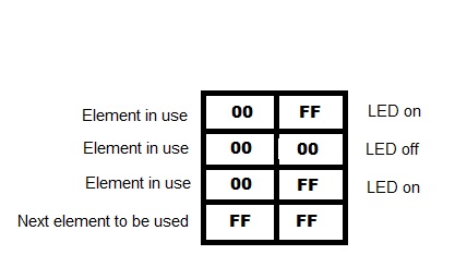
But there is a simple solution for this. Instead of using the same byte over and over to keep track of the on or off status, one can use an array of bytes, which fill up the entire chip.

You need two bytes for each element in the array. So a 64 byte EEPROM, like the one in the PIC16F84A, could hold 32 elements. Each time you write to the EEPROM, you write a 0 to the status byte (meaning this element has data), and either a 0 to the data byte (LED was last off) or a 0xFF (LED was last on). The next time you access the EEPROM, you index through the elements until you find one with a 0xFF status byte, and then use the that element. If there are none left, then re-initialize the EEPROM and start over (for the low-end PICs, this means writing 0xFF's to each of the status bytes; for the PIC24, there is a command to erase the whole EEPROM). If you need to know the last status of the LED, you index through the array as before, but now go back one element and read out the data byte.
enter image description here

This essentially divides the number of accesses to a single byte by a factor of 16 for the PIC16F84A (16 and not 32 because each of the status bytes is written to twice). So it would be able to handle 16 million writes total, enough for almost four years of data. And the PIC12F635 with its larger EEPROM but smaller byte endurance of 100K, would be able to handle 3.2 million writes total, enough for nine months.

The PIC24F16KA102, with its 512 byte EEPROM and bulk erase feature, would be able to handle 25.6 million writes, enough for over five years.

If the blinking rate was only four times per hour instead of four times per minute, then this means a total of 70,080 writes per year. Even the PIC12F635, with its endurance of 100,000 writes per byte, would last would last 45 years!
\$\endgroup\$
9
  • 1
    \$\begingroup\$ You could refrain from writing to EEPROM until after a loss of power. The capacitors should store enough charge to keep the uC running long enough to write the current state. This could greatly increase the longevity of your EEPROM. \$\endgroup\$
    – MichaelS
    Commented Sep 2, 2015 at 5:13
  • \$\begingroup\$ Also, why not use multiple bits per byte? First byte stores 7 bits of counting data and 1 bit of LED data. The first time you write, you set the byte to 0000001L, then 0000010L, etc. When it reaches 1111111L, you reset the next byte to all zeroes. After getting to the last byte, you reset the first byte to zeroes. Then your next read location is the first byte whose top 7 bits are 0 < 7-bit <= 127, and the next write location is the first byte with 7-bit < 127. Now you've almost doubled your accesses because (almost) every write is to a single byte instead of two. \$\endgroup\$
    – MichaelS
    Commented Sep 2, 2015 at 5:22
  • \$\begingroup\$ @MichaelS I thought of that also. First, you can't go from 11111110 to 11111101 because you can't write 1's (I inverted your starting condition.) Instead you'd write 0's, one at a time across the byte. But it doesn't really do any good in terms of limiting the number of writes per byte -- you end up having to write to each byte eight times instead of once. \$\endgroup\$
    – tcrosley
    Commented Sep 2, 2015 at 6:43
  • \$\begingroup\$ I haven't used the exact PIC devices in question, but my understanding is that you erase all the data, then change any bits that shouldn't be default at once. So if "erased" means all 1s, then you'd erase everything and change bits 1-6 and possibly L. Next, you'd erase everything and change bits 1-5, 7, possibly L. Towards the end of the count, you'd only be changing a few bits (1110110L -> 1110111L only changes bit 4 and L). Because there's a 50% chance per erase, and 50% per write, for a given bit to get erased, it's an average of 100%, or 8 bits per erase/write cycle. \$\endgroup\$
    – MichaelS
    Commented Sep 2, 2015 at 7:14
  • \$\begingroup\$ With your method, the entire status byte gets erased some time before use, then set to zero on use, or 16 bits per erase/write cycle. At the same time, your entire data byte has a 50% chance per erase, 50% chance per write, or an average of 8 bits per erase/write cycle. The total is then 24 bits per cycle. Even if we assume each erase/write cycle is equivalent per byte, it's still two bytes changing instead of one. (Can't edit the above comment, I meant 50/50 for a given bit to get changed, not erased, in the last sentence.) \$\endgroup\$
    – MichaelS
    Commented Sep 2, 2015 at 7:19
2
\$\begingroup\$

This may be a very naive suggestion... but how about about building a low-powered transistor latch driven by a button battery. Then use the output from that to feed into an OP-amp that is driven by the power supply. That way you unload the button battery of the strain of feeding the useful output; you cannot use that anyway while the supply is turned off, right?

EDIT: Also - according to comment below - it is advisable to make it so that the latch is isolated from the OP-amp if the supply goes away. Any kind of relay - or equivalent circuit - that is fed by the supply should be able to do the job there.

Considering that a simple wrist watch can be driven by a button battery for years, powering a simple latch should give it a life-time per battery that lasts a decade. You can even put two batteries in parallel so that you can swap them out - one at the time - without losing the information.

\$\endgroup\$
2
  • 1
    \$\begingroup\$ There are only very few Op-Amps available which allow a voltage at the input higher than the supply voltage, which would be the case during shutdown. \$\endgroup\$
    – Arsenal
    Commented Sep 2, 2015 at 11:46
  • \$\begingroup\$ If that is the case, isn't there a way to shut off the input to the OP-amp if the supply goes away, essentially isolating the latch? Any kind of relay - or equivalent circuit - would do the trick there, would it not? \$\endgroup\$
    – MichaelK
    Commented Sep 2, 2015 at 12:09
0
\$\begingroup\$

A small CPLD can be programmed to drive the protocol needed to write a simple set of values to an I2C bus.

NXP make a range of very small memories, intended to replace dip switches, e.g. PCA8550 / PCA9561.

Combine the two and you have a very small solid state switch that remembers it's state.

\$\endgroup\$

Not the answer you're looking for? Browse other questions tagged or ask your own question.