1
\$\begingroup\$

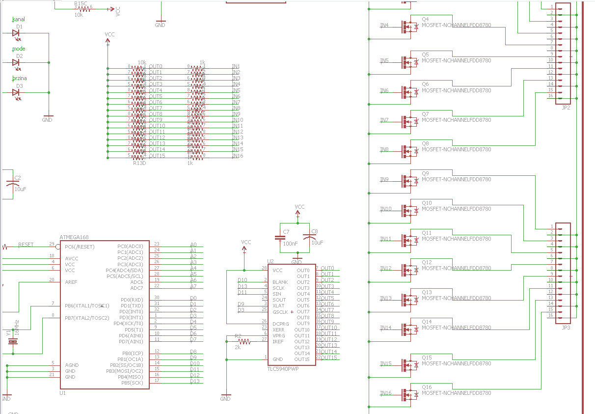
I have been doing some project which worked for few months and then MOSFETs started burning. Here is detail of schematic:

schematic

So, we are using:

  • NTD4963MT4G MOSFET (datasheet)
  • TLC5940
  • some 1k and 10k resistors

Microcontroller is Atmel Atmega328(Arduino bootloader, basically Arduino) which communicates with TLC5940 and controls TLC's outputs. Those 16 outputs are connected to MOSFETS.

From output of TLC there in a 1k resistor in series with gate and there is also 10k pull-up transistor on gate(to turn off MOSFET faster). Source of the transistor is connected to ground. Drain of transistor is connected to the load. Positive terminal(+) of load is directly connected to power supply positive terminal.

Riref resistor on TLC is 2k, which equals at 31,5*1,24/2000 = 19mA per channel.

Actual load are LED lights. Power of LED light on each channel is max. 15W.

Behaviour(code at Atmega) is to do various things with outputs, blink, fade etc.

Thanks anyone who puts thier time into resolving this issue.

EDIT: here are more details I, seems to be, forgot:

  • Vcc is chooseable. It can be 5V, in that case uC and TLC, but LEDs too, are supplied directly from power supply. It can be 12V, also, then via regulator 5V is used for uC and TLC, but on MOSFETs there are 12V.
  • TLC frequency is default, which is (I think)517,2Hz
  • Schematic shows FDD8780 just because they have same footprint. NTD4963MT4G are actually used.
\$\endgroup\$
2
  • \$\begingroup\$ How come the circuit diagram shows FDD8780 FETs? What value is Vcc? \$\endgroup\$
    – Andy aka
    Commented Sep 7, 2015 at 16:46
  • \$\begingroup\$ Another point I would make (although I doubt it it the cause unless you're doing high frequency PWM) is that your TLC5940 can't source current, and hence can't actually drive the MOSFET hard on - you're relying on the 10k pullups to do all your positive current sourcing, which means that your turn-on will be slower than you would achieve even with a simple 74HC595 or similar. This only makes a difference at turn-on, however, so if your PWM frequency is slow (up to 10s of kHz) you're unlikely to see extra dissipation this way. \$\endgroup\$
    – stefandz
    Commented Sep 7, 2015 at 17:03

2 Answers 2

1
\$\begingroup\$

There are three possible causes I can think of that would cause the FETs to be damaged:

1) Over dissipation. You say the LEDs are 15W - how much current is that? Do the FETs get hot?What voltage are they being driven from? How fast is the multiplexing from the TLC5940? If the gate drive is not enough to ensure saturation they could get excessively hot and be damaged.

2) Over voltage. You have no snubbers (an R and C) on the outputs to dissipate voltage spikes if there is inductance in the wiring, you could get these spikes at turn-off of the FETs.

3) SOA violation: Is there excess capacitance on the output lines that could cause excessive currents at turn-on of the FETs.

To start with I would look in detail at the turn on and turn off of the output stages. Ensure there is enough gate drive, that the drain voltage goes down to a very low voltage when the FET is on. Look for spikes at the drain when the FET turns off.

Looking at the FET current is not so easy - a low value resistor in the source of one of the FETs would be one way or a current probe.

\$\endgroup\$
1
\$\begingroup\$

From your description, you are connecting the MOSFETs directly in series with the voltage source and LEDs. When dealing with LEDs we always need current limiting resistors in series to limit the current.

Without a current limiting resistor, the voltage source is simply across the LED and a large current will be flowing through the MOSFET and diode, causing the MOSFET to burn. To calculate the current limiting resistor, you should first determine the current you want flowing through your LED based on the desired brightness. Then it's a matter of (VCC - V_LED) / R = I_LED, solve for R. See your LEDs datasheet for the relationship between brightness and current.

I would be cautious of how you are using the TLC5940. The TLC5940 is a LED driver, not a MOSFET gate driver. While the TLC5940 does have current limiting, it is limiting the amount of current flowing into the gate of the MOSFET, not the current flowing through the MOSFET (Drain to Source).

I would modify the circuit in 1 of 2 ways. First, add the series current limiting resistors to the LED loads. This should limit the amount of current flowing through the MOSFETs and fix the issue burning the MOSFETs. Second, the TLC5940 actually already provides constant current control. Thus, you could attach LEDs directly to the TLC5940 and it will take care of limiting the current. Now your R_iref would actually be meaningfully controlling the correct current and you don't even need the MOSFETs.

Lastly a few comments on the gate drive circuitry. 1k gate resistors seem very large. These series resistors limit how quickly the gate of the MOSFET can charge and discharge as you have noted. It can also help avoid oscillations on the MOSFET gate. However as we increase the gate resistance, more time is spent transitioning between ON/OFF. There is large power dissipation during this transition and it is wise to keep these transitions short. Something on the order of 10-100 ohm might be more appropriate. Additionally, the 10k pullups to VCC should not make MOSFETs turn off faster. We are using NMOS devices, so OFF is equal to a low input voltage. By weakly pulling the gate high, these resistors are attempting to turn the gate on. I don't particularly think fast turn offs are necessary in this application either, but the standard way of implementing fast turn offs are having a diode placed between the control terminal and the gate. During turn-on, the diode is reverse biased and all current flows through the gate resistor, slowing down the turn-on. During turn-off, the control terminal is grounded and the gate is high. The diode is forward biased and the gate can discharge through the diode for a quick discharge. See this question

\$\endgroup\$

Your Answer

By clicking “Post Your Answer”, you agree to our terms of service and acknowledge you have read our privacy policy.

Not the answer you're looking for? Browse other questions tagged or ask your own question.