0
\$\begingroup\$

I'm trying to wake up my Arduino and run some code when a reed switch or SPST switch connected to an interrupt is opened. If my Arduino is in powered off mode, only LOW interrupts are accepted (not changes, which would make things much easier).

Is there a simple hardware way to send a single LOW pulse when the switch is disconnected? I'm trying to avoid the interrupt continually triggering my Arduino to wake up while the switch is open; I only need the code to run once, and then I want my Arduino to power back off until the switch is eventually closed and then reopened again.

I've been exploring using a 555 timer in monostable mode, perhaps with a transistor inverter to make the pulse low, but it appears that that solution will eventually trigger again (more than once) if the reed switch remains open for a prolonged period.

\$\endgroup\$
1
  • \$\begingroup\$ What about using pull-up resistor? \$\endgroup\$ Commented Sep 10, 2015 at 18:12

3 Answers 3

2
\$\begingroup\$

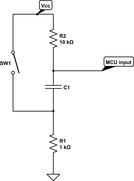
Sounds like capacitively coupling it might work well. Reed switch goes from power a pull-down resistor and one side of the cap. The other side of the cap goes to a pull-up resistor and the GPIO pin. When the reed switch is closed, both sides of the cap will sit on the power rail. When you open the switch, the pull down resistor will pull that side of the cap down. If the cap is large enough and the resistors are properly sized, the GPIO pin will be pulled down as well until the cap can charge up. When the switch is closed, the capacitor will discharge. It might be a good idea to add a clamp diode to power on the GPIO pin side of the cap so the cap can discharge through the diode instead of the chip's ESD protection diodes. You'll need to play around with the values of the resistors and capacitor to get a pulse of the right length, though the pull-down will have to be significantly smaller than the pull-up - I would suggest trying a 10k pull-down with a 100k pull-up. To figure out about how long the pulse will be, calculate the time constant, tau = RC. This will be approximately how long the pulse will be. A 10k and 100k resistor with a 0.1 uF capacitor will give you a tau of about 110e3 * 0.1e-6 = 0.011 seconds.

\$\endgroup\$
2
  • \$\begingroup\$ This sounds like it could work well; thanks. I'm having some difficulty visualizing the circuit as I'm super new to EE, also not sure where the diode would go \$\endgroup\$ Commented Sep 11, 2015 at 17:48
  • 1
    \$\begingroup\$ Andy was nice enough to draw up the exact circuit that I described, just without the diode. The diode anode would go to the GPIO pin, and the cathode would go to Vcc. In this way, it will be reverse-biased when the voltage on the GPIO pin is less than Vcc. When the switch closes and the capacitor charges, the diode will clamp the voltage on the GPIO pin to Vcc+0.7 volts or so. \$\endgroup\$ Commented Sep 11, 2015 at 18:38
2
\$\begingroup\$

schematic

simulate this circuit – Schematic created using CircuitLab

\$\endgroup\$
6
  • \$\begingroup\$ I really appreciate the clarity and brevity here. C1 size alters length of pulse? \$\endgroup\$ Commented Sep 11, 2015 at 17:52
  • 1
    \$\begingroup\$ This is precisely the circuit I described in my answer, sans the diode. The RC time constant formed by the capacitor and the resistors will set the length of the pulse. One thing to note, though: R1 will conduct when SW1 is closed, so you may want to tune the size of R1 to minimize power consumption while the switch is closed. 1k will consume 5 mA when Vcc is 5V, which may be significant in your application. \$\endgroup\$ Commented Sep 11, 2015 at 18:40
  • 1
    \$\begingroup\$ @alex.forencich good call about current consumption \$\endgroup\$
    – Andy aka
    Commented Sep 11, 2015 at 19:23
  • 1
    \$\begingroup\$ Hence my recommendation of 10k and 100k. It might even be possible to get away with 100k and 1M, which would be 50 uA. This is also a consideration if you consider a one-shot timer or similar - the quiescent current draw may be unacceptable. \$\endgroup\$ Commented Sep 11, 2015 at 19:31
  • 1
    \$\begingroup\$ Honest I didn't read your words and make a circuit LOL \$\endgroup\$
    – Andy aka
    Commented Sep 11, 2015 at 20:35
2
\$\begingroup\$

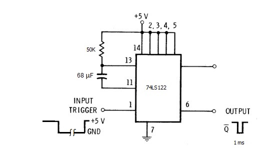
Along the lines of your investigating use of a 555, you might consider using a 74LS122 monostable. Using a monostable gives a nice square pulse on the output with a precise pulse width (depending on the tolerance of the resistor and capacitor).

Unlike the 555, the 74122 always generates the same length output pulse no matter how long the input is kept at ground.

enter image description here

The values shown for the resistor and capacitor will generate a 1 ms pulse.

If you are using a switch, you might want to increase the delay to 30 ms or so to mask any switch bounce. That would mean using a 2000 µF capacitor instead of 68 µF. Whether you need a delay longer than 1 ms for the reed relay will depend on the specs for the relay.

The 74LS122 is available in a 14 pin DIP package for $1.25

\$\endgroup\$
2
  • \$\begingroup\$ This looks great! So it only gives one pulse until the input toggles again? \$\endgroup\$ Commented Sep 11, 2015 at 17:51
  • 1
    \$\begingroup\$ @VictorVanHee Yes, regardless of pulse length. \$\endgroup\$
    – tcrosley
    Commented Sep 11, 2015 at 18:02

Your Answer

By clicking “Post Your Answer”, you agree to our terms of service and acknowledge you have read our privacy policy.

Not the answer you're looking for? Browse other questions tagged or ask your own question.