How does one calculate the input impedance of a differential amplifier?
Since the input impedance of an op-amp is very high, the input impedance for V2 should be R2 + Rg. But what would be the input impedance for V1?
How does one calculate the input impedance of a differential amplifier?
Since the input impedance of an op-amp is very high, the input impedance for V2 should be R2 + Rg. But what would be the input impedance for V1?
Differential input impedance is the ratio between the change in voltage between V1 and V2 to the change in current.
When the op-amp working, the voltages at the inverting and non-inverting inputs are driven to be the same. The differential input impedance is thus R1 + R2.
If the op-amp was 'railed' (saturated) then the differential input impedance would be higher: R2 + Rg + R1 + Rf.
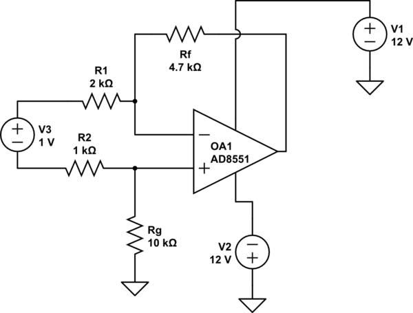
Here is a circuit that can be simulated, based on the above definition of differential input impedance (values picked to be different). The input current is 333.3uA = 1V/3K.
simulate this circuit – Schematic created using CircuitLab
Edit: To summarize the discussion with Dave Tweed below in comments, there are three impedances we can calculate.
The differential input impedance is R1 + R2 as stated above.
The input impedance looking in from V2 is R2 + Rg.
The input impedance looking in from V1 is R1 (assuming the op-amp is functioning and not saturated). That is because the voltage at the inverting input is driven by the op-amp to be the same as the voltage on the non-inverting input, and it does not depend on the value of V1, only on V2.
The first two impedances have no voltage sources associated with them. The third one has a voltage with respect to ground of \$V2 Rg\over {Rg + R2}\$, so current will flow in or out of the V1 terminal depending on whether V1 is higher or lower than that value.
The proposed TI material brought up this question from 8 years ago and it caught my attention. Looking at the author's efforts to explain qualitative things (ideas) with quantitative means (formulas), I remembered that many times I tried to understand famous circuit solutions (Howland current source, improved Howland pump, etc.) from such TI, NI, AD and others company materials sources... and I have seen this approach everywhere. The same problem appeared when math entered simulators, and now it has become very relevant with the advent of artificial intelligence with its claims to "explain" and "understand".
My belief is that these are tools that only aid understanding... but do not replace it. Understanding means seeing the most general idea in a particular circuit solution that can be observed in many other implementations. So let's see what the idea of the input resistance problem of this famous circuit is.
The resistance of the inverting input of the op-amp differential amplifier is not constant but depends on how the input signals change. This phenomenon can be explained by the Miller effect in its generalized form in the Miller theorem. It states that if we connect in series to the input voltage source an additional proportional voltage source, we can artificially change the input resistance. If the source is connected so that its voltage is added to the input voltage, the resistance is reduced because the current is increased; if its voltage is subtracted from the input voltage, the resistance increases because the current decreases. In the particular case, the input resistance is modified because the input voltage Vin1 is applied to the R1 left end and a (copy of) part of the input voltage Vin2 is applied to its right end. In fact, R2 and the entire network R1-R2 are modified accordingly. Let's consider the most typical cases.
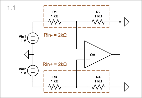
Let's initially imagine that the op-amp has stopped working and its output voltage is zero (I have simulated this in a somewhat "brutal" but reliable way by simply grounding the output). Both input voltage sources "see" 2 kΩ equal resistances: Vin1 sees R1+R2, and Vin2 sees R3+R4.
simulate this circuit – Schematic created using CircuitLab
The latter does not change because it is permanently grounded, so we will only deal with the former in the future.
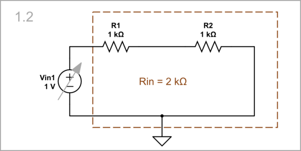
Let's sweep Vin1 and plot the current to get an idea of the input resistance by the slope of the IV curve. Ignore the yellow horizontal line here and below; I put it only to "cheat" the CircuitLab autoscaling.
If we fix Vin2 (e.g. at 0 V), the op-amp maintains the voltage at the right end of R1 at 0 V (the so-called virtual ground).
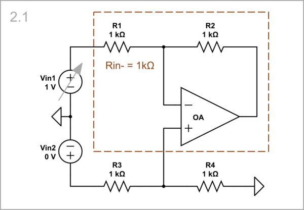
In effect, the op-amp adds as much voltage as is dropped across R2, and thus compensates for it. The op-amp output can be considered as a "negative resistor" with -1 kΩ resistance that neutralizes the 1 kΩ "positive resistance" R2, and the resulting resistance is zero.
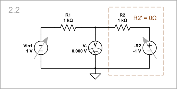
Figuratively speaking, the right part of the circuit behaves like a "piece of wire".
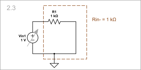
The IV curve of the input resistance is twice as steep.
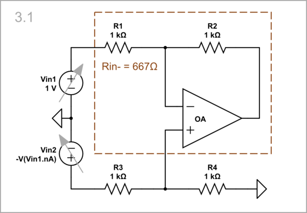
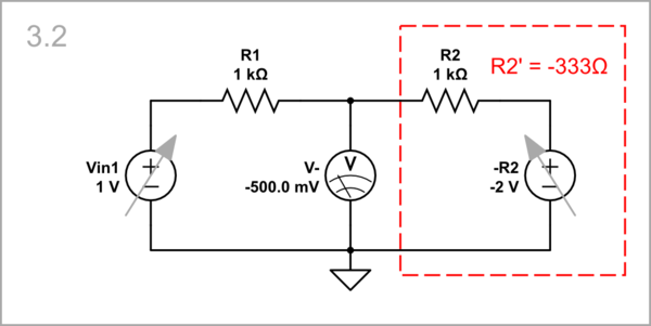
Vin2 = -Vin1 is a much more interesting case that has attracted the attention of the author who wrote the TI material. Here the op-amp is forced to drop its voltage further below zero (-2 V) to set -500 mV to its inverting input (which is no longer virtual ground).
In effect, the op-amp adds more voltage (2 V) than is dropped across R2 (1.5 V), and with the remaining 500 mV compensates part of the voltage drop across R1. The op-amp output can be considered as a "negative resistor" with -1.333 kΩ resistance that neutralizes the 1 kΩ "positive resistance" R2, and with the remaining -333 Ω compensates 333 Ω of the R1 "positive" resistance.
Thus the resulting input resistance is 667 Ω. Notice that there is still a virtual ground, but it is inside R1. In order to "see" it without opening R1, we can replace it with a potentiometer, and find it by moving the wiper.
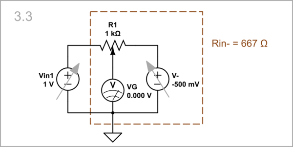
The input resistance IV curve is even more steeper as above.
Vin2 = Vin1 is analogous to the initial Case 1 but with a functioning op-amp that sets its output voltage to zero by itself. The "virtual ground" is "lifted" by 500 mV and the input resistance is 2 kΩ.
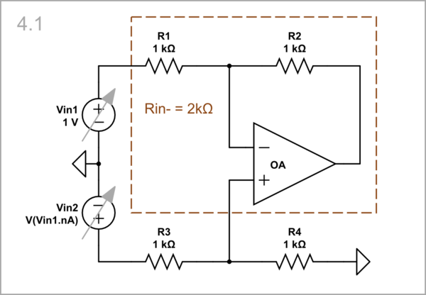
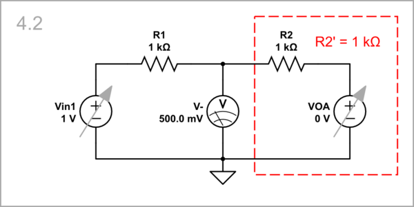
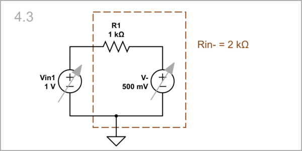
This is the famous bootstrapping arrangement where the op-amp maintains the voltage at the right end of R1 equal to the voltage (Vin1) of its left end.
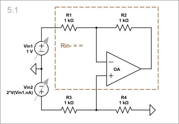
As a result, no current is drawn from Vin1...
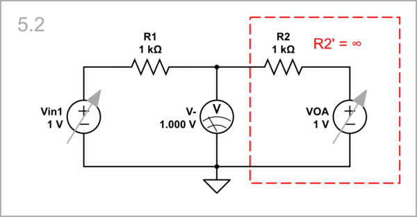
... the input resistance is infinite...
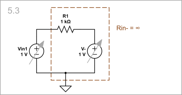
... and the IV curve is horizontal.
In the circuit of the op-amp differential amplifier, the op-amp modifies the input resistance of the inverting input by adding/subtracting its output voltage to/from the V1 input voltage.