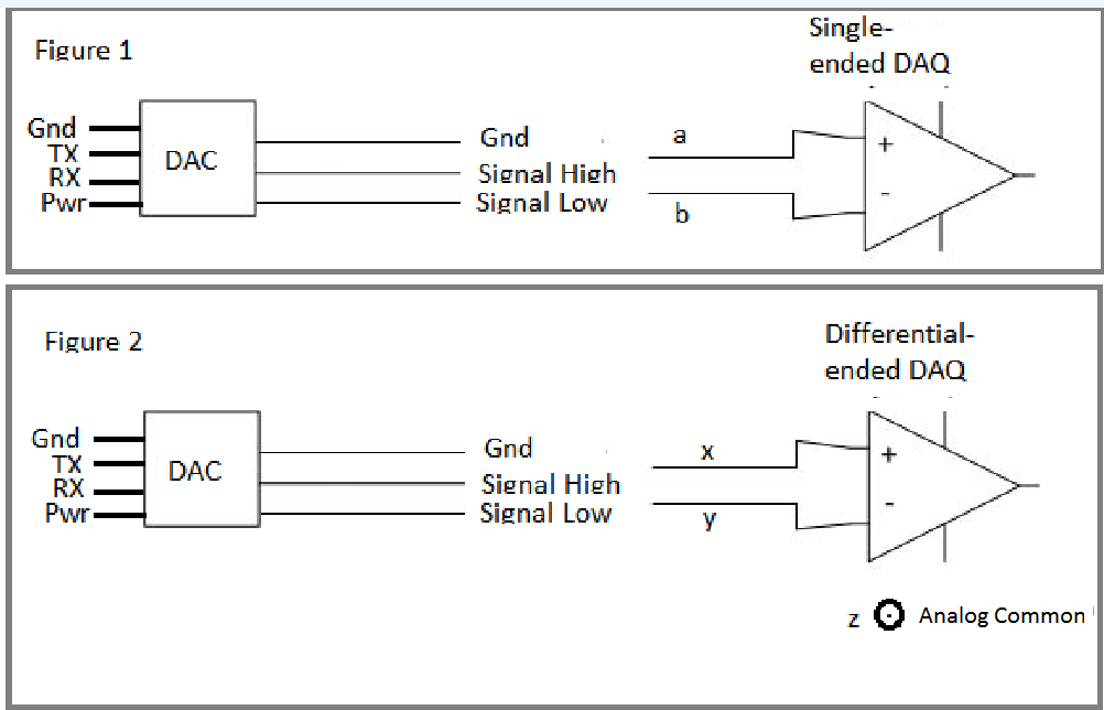
 When I connect a digital to analog converter(as shown in Figure 1) to a single-ended data-acquisition hardware I noticed that the signals are upside down. It seems like the DAC is providing differential ended output signals. Because when I connect Signal-high to + of DAQ(“a” in the figure) and GND to the – of DAQ channel(“b” in the figure) I got the mirrored(upsidedown) image of in the case of Signal-low to + of DAQ(“a” in the figure) and GND to the – of DAQ channel(“b” in the figure). But when I connect Signal-high to + of DAQ(“a” in the figure) and Signal-low to - of DAQ(“b” in the figure) there is no signal rather than some noise.
Now I’m planning to use the following differential ended DAQ hardware: http://www.mccdaq.com/PDFs/manuals/USB-1616HS-BNC.pdf Regarding Figure 2 in my drawing I’m going to connect Signal-High to “x”, and Signal-Low to “y” since it is diff-ended DAQ. This DAQ has also an Analog Common pin. Should I connect this pin to the GND of DAC.
I checked with a multimeter’s continuity mode and found out power supply’s GND which goes to DAC and DAC’s output GND are all connected. Would it be safe to connect Analog common to the the GND of DAC.
