2
\$\begingroup\$

EDIT: See last paragraph

I recently got a cheap 2-channel oscilloscope (Hitachi V-212). Judging from the "calibration not required" sticker on the front, it's been beaten up and/or neglegted (by the police, no less!) for several years.

I've found the relevant service manual and have correctly adjusted the really easy things like DC offsets etc (and don't worry: I'm staying away from the high voltage CRT end).

However, I don't understand what's going on with the calibration signal. It claims to be a 1kHz square wave and the loop sticking out the front is marked "CAL .5V". There are two confusing things:

  1. When I connect up a X1 oscilloscope probe between the calibration and the input, I don't get a square wave at all. Instead I get sudden jumps in both directions from zero (presumably the leading edges) and a fast exponential decay back down to the middle. (I would take a photo, but I don't own a digital camera - sorry!)
  2. Also, the "square wave" is best visible when VOLTS/DIV is set to 5 or 10mV. This doesn't seem to agree with the "0.5V", but the service manual suggests checking x1 AC GAIN by settings VOLTS/DIV to 10mV and connecting to the calibration signal, so maybe I misunderstood something.

I'm not too concerned about the second part - it's something I don't understand rather than something I want to fix... But can anyone tell me what's wrong with my "square wave"? Am I using my probe wrongly (it's an adjustable x1/x10 probe, but I have it set to x1)? Or could the calibration signal be wrong? Or is it the oscilloscope's actual measuring system?

I've used oscilloscopes (some time ago) at school, so I understand vaguely how things work, but (of course) they were all in good nick so I've never had this sort of question.

Thanks for any help!

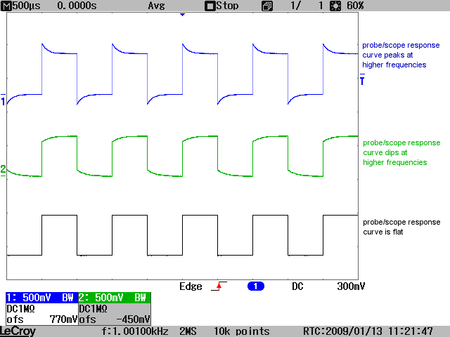
EDIT: Hmm, I just tried a different probe and everything looks fine (ie very slightly like the blue trace in stevenvh's example, but easily fixable). I take it that something's wrong with the probe.

\$\endgroup\$
1
  • \$\begingroup\$ when you see a 'calibration required' sticker, especially on something owned by an institution, it doesn't necessarily mean that there's something wrong with the piece; it's usually just a company policy to ensure equipment doesn't get so far off cal as to be untrustworthy. That said, it's a good idea to cal your own equipment on a regular basis anyway. \$\endgroup\$
    – JustJeff
    Commented Sep 10, 2011 at 14:51

2 Answers 2

4
\$\begingroup\$

enter image description here

The distorted square wave signal (something like the top trace?) is due to a mismatch between your probe's capacitance and the scope's input's capacitance. Your probe should have a tiny screw-like slot to adjust the capacitance. Turn it until you see a proper square wave.
The low level you see is probably due to the probe being set to its 1:10 position.

\$\endgroup\$
3
  • \$\begingroup\$ I don't think that the probe is at the 1:10 position: there is a three-position switch (X1, REF, X10) and the signal is further attenuated when I move it to X10. Turning the screw doesn't seem to make a significant difference on either of the two settings (also, would I expect it to do so at only 1kHz?) \$\endgroup\$ Commented Sep 10, 2011 at 10:39
  • \$\begingroup\$ Answering the edited version with the picture: yes, it's more like the blue version but where the exponential decay goes right down to the middle from both sides in maybe 10% of the total time. \$\endgroup\$ Commented Sep 10, 2011 at 10:44
  • 1
    \$\begingroup\$ Hmm, I've just tried a different probe and things look fine. Thanks for the help: I suspect that the first probe was leaking to ground in some way. Grr. \$\endgroup\$ Commented Sep 10, 2011 at 11:32
5
\$\begingroup\$

From your description it sounds like there may be a tiny break in continuity somewhere or a dry joint, with enough capacitance present to couple the high frequency AC but ignore the DC.
Wiggling the cable whilst applying calibration signal may intermittently make it work properly again.

A simple way to test this would be too see if it works with a DC voltage (e.g. battery) at all. Or test for continuity with a multimeter.
If results indicate the worst, the biggest suspect is probably the BNC connector junction. If you can unscrew it (not moulded) then have a look and see if contacts are bad.

\$\endgroup\$
1
  • \$\begingroup\$ Ah, that makes sense. And, yep, there's no DC response. The junction's moulded so I'm going to try grumbling at the person who sold me the probe first... Thank you for the help! \$\endgroup\$ Commented Sep 10, 2011 at 19:30

Your Answer

By clicking “Post Your Answer”, you agree to our terms of service and acknowledge you have read our privacy policy.

Not the answer you're looking for? Browse other questions tagged or ask your own question.