3
\$\begingroup\$

I've just started learning EAGLE and I've been trying to make a PCB to mount some LEDs on. I read through a few online tutorials, and I believe I have (correctly?) made the schematic in EAGLE.
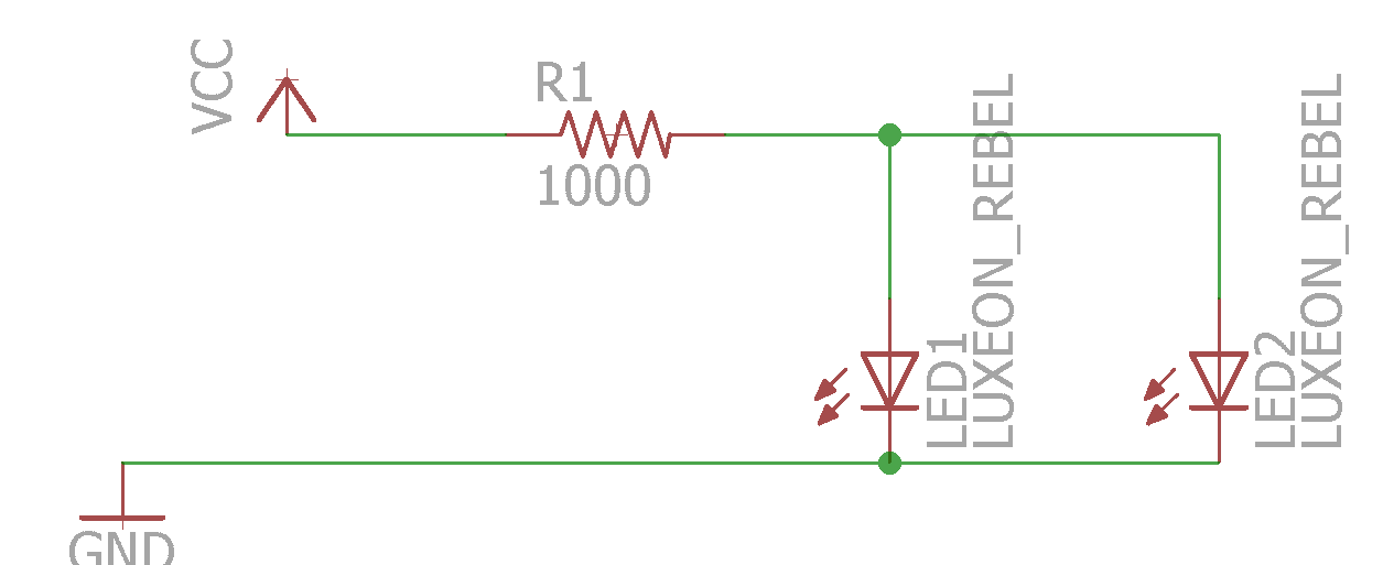
Schematic But when I error check, it gives me 2 warnings. There is only one pin on net VCC. One is where the VCC connects to the net and the other where the same net connects to the resistor. I can't seem to find any information on what the issue is or how to fix it.

When I switch to the board layout, I only have the resistor and the two LEDs. How am I supposed to get the VCC and GND pins on the board? Are they even supposed to be there? All the tutorials I've found online include some part with included voltage and ground pins so the entire package shows up on the schematic.

\$\endgroup\$
1
  • 3
    \$\begingroup\$ You need separate resistors for each LED. If one has a slightly lower forward voltage drop than the other, it will get all the current. I'm not saying that if you have 2 LED's of identical part number from the same batch you will still have a problem, but it's bad practice. The other way to avoid the problem is to put the LED's in series, but you can only do that if you have a power supply with high enough voltage (say about 5V). \$\endgroup\$ Commented Oct 2, 2015 at 20:20

5 Answers 5

3
\$\begingroup\$

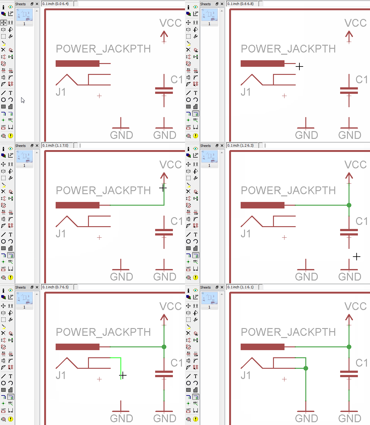
If you want VCC and ground pins, you need to add components for those. The VCC and GND symbols you have are ports. Any pins connected to VCC are considered connected to each other, and the same goes for GND. This tutorial shows an example of a DC jack component that provides an off-board connection for VCC and GND:

Power jack hookup from AVR Eagle tutorial

\$\endgroup\$
2
\$\begingroup\$

The Vcc and Gnd symbols just assign names to those nets - they don't represent any real component.

If you need something to connect an external power supply to, you need to place a connector, with its pins connected to the Vcc and Gnd nets. For single wire connections, I make a suitable schematic symbol with one pin, and use a single pad as the PCB footprint.

\$\endgroup\$
2
  • \$\begingroup\$ Can you elaborate on how to do this or provide any useful links? \$\endgroup\$ Commented Oct 2, 2015 at 17:06
  • \$\begingroup\$ I only attempted to use Eagle once, so don't recall the detailed procedure. However, Eagle should have a schematic symbol editor and a PCB footprint (or is it called "decal") editor which would be used to make the appropriate symbols in the same way you would make symbols for any other component. \$\endgroup\$ Commented Oct 2, 2015 at 17:24
1
\$\begingroup\$

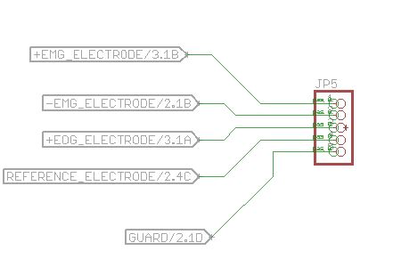
You need to put some kind of connector, or at least a solder point, for these kinds of things. One package that is relatively easy to use for such things is the PINHEAD library of 0.1" connectorsenter image description here

This is the device PINHD-1X5 from the pinhead library. I used named nets and labels to connect things to it.

\$\endgroup\$
1
\$\begingroup\$

Another option is to use the component called SOLPAD. As the name suggests, it creates a solder pad in the board.

You can find it in the library with the same name, and there's various pad sizes you can choose.

\$\endgroup\$
0
\$\begingroup\$

You can name the connecting wires in your diagram to VCC and the autorouter will attempt to connect them all together.

I also use the plane technique, I draw a polygon on the lower layer of the board and then name it GND, I draw another on top and name it VCC.

You have to create through-hole connectors for SMD devices but just by running ratsnest function, it connects VCC and GND for through hole devices.

This, of course, implies double-sided boards and has the advantage of creating a capacitor between VCC & GND planes, it's also known to reduce RF emissions from boards.

\$\endgroup\$
1
  • \$\begingroup\$ Welcome to EE.SE. The site rules recommend proper punctuation, capitalisation and grammar. It helps legibility and your credibility. Use <Enter> x 2 for paragraph breaks. \$\endgroup\$
    – Transistor
    Commented Jul 8, 2018 at 9:08

Your Answer

By clicking “Post Your Answer”, you agree to our terms of service and acknowledge you have read our privacy policy.

Not the answer you're looking for? Browse other questions tagged or ask your own question.