1
\$\begingroup\$

The question is basically: why use capacitor in this particular DC circuit? Generally, as I read in the thread below, using a capacitor in DC circuit may have different reasons and purposes. Given my lack on knowledge in the topic I do not know what is the reason for using it here.

What is the role of capacitors in DC circuits like motherboard, graphic card etc?

test

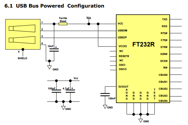
Here I am talking about the 10nF capacitor right after USB GND. Basically it connects USB GND with USB VCC. Given that USB is DC isn't it just a break in the circuit? Or, if we assume that some significant current can actually flow there, wouldn't we be causing s/c?

I understand that that this partial circuit shown at the bottom of the picture is something we could use instead of this 10nF and ferrite bead setup. So my thinking is that all these capacitors are here only for some EMI filtration. Is that correct? If yes, why is it so important to filter it here on the power terminals rather than maybe data terminals? Will it cause problems if we skip it completely? And why we are doing nothing with the data terminals? Thanks.

The picture comes from http://www.ftdichip.com/Support/Documents/DataSheets/ICs/DS_FT232R.pdf

\$\endgroup\$
1
  • \$\begingroup\$ it is DC, but can be over 1m away \$\endgroup\$
    – user16222
    Commented Oct 3, 2015 at 17:19

2 Answers 2

2
\$\begingroup\$

The data terminals in USB are high speed differential lines, you don't want to put any capacitance on those lines (it would kill your signal basically). You want to use some ESD protection devices on the data terminals though, to protect the data pins from getting destroyed by static discharge.

The 10nF capacitor on the 5V line together with the ferrite bead will filter out some noise picked up from the cable but also coming from the FTDI chip. So it will improve the EMI performance and will not disturb your USB host.

I don't think the bottom part is optional but mandatory as well. The 4.7µF capacitor will store some energy which will acts as a pool the FT232R can take from without the parasitic inductance and resistance of the wire affecting it much. The 100nF capacitor is just your standard value decoupling capacitor to improve the noise performance of the FT232R.

The 10nF capacitor is not a break in the DC circuit. As you can see the GND node is also on the GND pins on the FT232R, so the current will gro from VCC through the FT232 to the GND node and back to the host.

\$\endgroup\$
5
  • \$\begingroup\$ Similar answer to mine so we must be right then :-) \$\endgroup\$ Commented Oct 3, 2015 at 17:33
  • \$\begingroup\$ @FakeMoustache similar timing as well :-D \$\endgroup\$
    – Arsenal
    Commented Oct 3, 2015 at 17:34
  • \$\begingroup\$ Thank you for the answers FakeMoustache and Arsenal. I understand that these 4.7 and 100nF capacitors can be put anywhere on the VCC wire? Is there a known practice of showing integral parts of a whole circuit as a "free floating" excerpt? Why not put it together? \$\endgroup\$
    – user51704
    Commented Oct 3, 2015 at 19:13
  • \$\begingroup\$ @futer8 It is quite common to do that for power supply stuff as it will clutter up the schematic around the parts. If you put those away on the schematic it's easier to see the function. Any EE will know where to put the power supply stuff. And it's not anywhere. Decoupling capacitors must be put as close as possible to the power supply pins and typically you put one 100nF on each pin. There are good questions and answers about decoupling capacitors here. I'm not sure about the placement of the ferrite and 4.7nF cap though. \$\endgroup\$
    – Arsenal
    Commented Oct 3, 2015 at 19:30
  • \$\begingroup\$ @futer8 sometimes there will be a separate schematic only to show the power supply sections of the chips - but each approach has it's benefits and downsides. \$\endgroup\$
    – Arsenal
    Commented Oct 3, 2015 at 19:31
2
\$\begingroup\$

"Given that USB is DC isn't it just a break in the circuit?" USB has 5 V DC on pin 1 and ground on pin 4, that IS DC. The signal (AC) is on pins 2 and 3. The 10 nF capacitor is for DC decoupling, it has nothing to do with the USB data signal.

Decoupling the data signals like that would not be a good idea, the data would not be able to get through.

Sure probably you could leave it out and thing might still work. But it is good practice to decouple, it can prevent problems that are difficult to diagnose.

No these capacitors are not only for EMI suppression, all CMOS circuits (and 99 % of ICs are these days) need decoupling on their supplies. When a CMOS gate switches it very briefly draws a current peak. If there was no decoupling, the supply could drop resulting in unexpected behaviour, the pulse might need to follow a long path causing RF signals to be transmitted.

In this particular circuit indeed, nothing is done with the data lines from the FT232 but this circuit is just an example, normally a serial interface or SPI bus would be connected to these signals.

\$\endgroup\$
2
  • \$\begingroup\$ Excuse me, I have a hard time finding a polarized 10nF capacitor, but I have an unpolarized 0.1uF ceramic one. In your opinion, would it be a suitable substitute? I can test, of course, but I am afraid to blow up an expensive computer. Also, could it be they at FTDI made a mistake and instead meant 10uF (microfarads) one instead of 10nF? \$\endgroup\$ Commented Apr 22, 2020 at 7:23
  • 1
    \$\begingroup\$ @ArthurTarasov Polarized 10nF caps are non existing as far as I know. But you're overthinking these capacitors. They're just for supply decoupling. 100 nF is fine 10 nF is fine as well but a bit small. 10 uF will do as well. It doesn't really matter. Also polarized or not: it doesn't matter. There needs to be a capacitor and the default choice is 0.1 uF = 100 nF. Just use that 100 nF and move on. \$\endgroup\$ Commented Apr 22, 2020 at 7:41

Your Answer

By clicking “Post Your Answer”, you agree to our terms of service and acknowledge you have read our privacy policy.