0
\$\begingroup\$

For my senior design project, I am trying to generate two voltage levels or rails from a battery powered circuit (12 V and 3.3 V.)

I am using an adjustable boost converter for the 12V rail and a fixed one for the 3.3 V.

The battery is a Li-ion 3.7 V_nom, 2200 mAh from Tenergy.

The boost converter is the ADP1613 and I also have a backup, the LM2735.

The 3.3 V is the LD3985M33R (buck.)

The loads I will be powering with the 12 V rail are:

  1. An electromagnet that draws a max of 450 mA according to the manufacturer (but in testing measured 150 mA)

  2. 4 strings of of 4 LEDs, running at 20 mA each, which puts each string at around 80 mA (the forward voltage is around 2 V for each LED)

  3. The bias voltage of an audio amplifier, the LM386N.

The 3.3 V is powering:

  1. An MSP430,

  2. A CC3200

  3. An LED driver.

The issue:

When I connect any load to my boost converter, the voltage output drops significantly.

For the electromagnet, it drops to around 4 to 5 V.

With the LEDs, it drops to around 7 to 8 V.

For the audio amplifier, it drops to around 6 to 7 V.

Unloaded, the boost converter provides around 12 V.

\$\endgroup\$
4
  • 2
    \$\begingroup\$ What inductor are you using for your boost converter? Datasheet of this part would be great. \$\endgroup\$ Commented Oct 5, 2015 at 23:37
  • 1
    \$\begingroup\$ Have you tried powering your converter from a lab supply? \$\endgroup\$ Commented Oct 6, 2015 at 6:03
  • \$\begingroup\$ Today i used the bench power supply at our lab, and set it to 3.6 V, with a possible 2.5 A output should i need it. That channel has a 6 V, 5A max rating. Testing still showed a drop in output voltage to about 4 V from 12 V. \$\endgroup\$
    – Joel
    Commented Oct 6, 2015 at 17:43
  • \$\begingroup\$ @Joel Did you ever get this to work? \$\endgroup\$
    – partoa
    Commented Jan 10, 2017 at 5:28

2 Answers 2

2
\$\begingroup\$

It sounds like that one or more of your components are not rated for the input current your stepup requires. You need to look closer at your battery and your inductor. You are roughly triple your output voltage of 12V, that means your input current will be about 3 times the output current: 800mA@12V = 2.5A@4V. Will your battery supply this current? Will it also supply the double amount if the switcher is drawing the current in pulse mode? Same for your inductor, is it rated for at least 5 Amps?

\$\endgroup\$
4
  • \$\begingroup\$ The data on what seems to be that tenergy.com/30004 cell is very skimpy. No C-rating or anything like that. Asking for 2.5A from an 18650 can be a bit much in my experience. rcgroups.com/forums/showthread.php?t=2120900 \$\endgroup\$ Commented Oct 6, 2015 at 6:01
  • 1
    \$\begingroup\$ The max. current on a regular LiPo battery should not exceed the capacity in mAh (=C). So for a 2200mAh battery the max. current draw would be 2200mA. That probably also has some tolerance. I personally would not go over 0.5C. In case of this application I would connect 3-4 of the batteries in parallel. \$\endgroup\$
    – optronik
    Commented Oct 6, 2015 at 13:09
  • \$\begingroup\$ I did try replacing inductors with different values. The ones I had originally were from eBay, so no datasheet, but the closest I found were these: taitroncomponents.com/catalog/Datasheet/TIA0204.pdf They are the 0410 Series. As i told the other responder, I tried using a bench power supply that is able to provide up to 5 A at my specified voltage, and it still dropped. \$\endgroup\$
    – Joel
    Commented Oct 6, 2015 at 17:46
  • \$\begingroup\$ Other questions are from reading online: -I am using electrolytic capacitors for my output and input. Could that be the issue? -Is the saturation current of the inductors an issue? -Could the feedback resistor divider be affected by the loads applied? -How does the Schottky rectifier diode affect the output under load? \$\endgroup\$
    – Joel
    Commented Oct 6, 2015 at 17:49
1
\$\begingroup\$

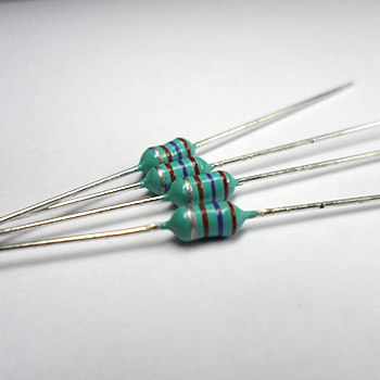
The TIA0204 inductors you are using are totally unsuitable: -

enter image description here

Read the data sheet - the maximum current (0410 series) is in the range 275 mA (100 uH) to 1700 mA (100 nH). The max current that your circuit will take from the LiPo is several amps.

\$\endgroup\$
0

Your Answer

By clicking “Post Your Answer”, you agree to our terms of service and acknowledge you have read our privacy policy.

Not the answer you're looking for? Browse other questions tagged or ask your own question.