0
\$\begingroup\$

enter image description here

I'm looking to calculate the voltage u(t) over L2 in this circuit however have run into some problem determining the current going into the transformer.

I know io and the relation N1/N2 and are using the impedance method.

My idea was to simplify the circuit by representing C1, L1 and R1 with only one impedance in parallel with io. Same thing for the right hand side. Finally I would calculate the current I1 going into the transformer using current branching. enter image description here
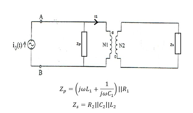
Now to the question. Is it possible to use current branching in this case?

From what I have learnt, since the transformer is ideal, the winding inductances of the transformer are infinite. Would not this however make the current going into the transformer 0 according to current branching?

This is schoolwork. no solutions please, just a push in the right direction :).

\$\endgroup\$

1 Answer 1

0
\$\begingroup\$

From what I have learnt, since the transformer is ideal, the winding inductances of the transformer are infinite. Would not this however make the current going into the transformer 0 according to current branching?

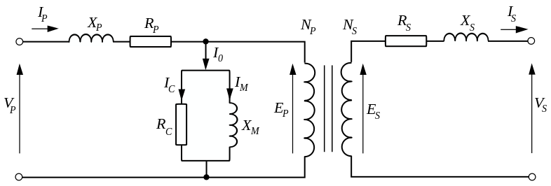
The magnetizing inductance is infinite and the leakage inductances are zero: -

enter image description here

So, for a perfect ideal transformer Xm is infinite and all the other inductors are zero. The transformer symbol in the middle should not be regarded as anything but a perfect power transmission device (even though it is drawn as two coupled inductors.

Rc is infinite and all the other resistors are zero.

Therefore the current does flow into the transformer.

\$\endgroup\$
7
  • \$\begingroup\$ So, if I have understood you correctly this means that the amount of current (I1) going into the transformer depends on the impedance's between the ideal current source and the transformer together with the load on the right side of the transformer? \$\endgroup\$
    – LaGranse
    Commented Oct 20, 2015 at 21:31
  • \$\begingroup\$ I'm struggling to see I1 in your's or my diagram. If it helps, the impedances seen on the primary side are those on the secondary side multiplied by the turns ratio squared. \$\endgroup\$
    – Andy aka
    Commented Oct 20, 2015 at 22:37
  • \$\begingroup\$ Edited the picture in the first post to include the current I1. What I was trying to say was: Is the branching such that if Zp is the impedance on the primary side and Zs the impedance on the secondary side then I1 is calculated as Zp*Io/(Zp+Zs)? Otherwise I must have misunderstood you when you said "The transformer symbol in the middle should not be regarded as anything but a perfect power transmission device". \$\endgroup\$
    – LaGranse
    Commented Oct 21, 2015 at 11:09
  • \$\begingroup\$ I'm sorry but I can't visualize this re the placement of Zp and Zs. \$\endgroup\$
    – Andy aka
    Commented Oct 21, 2015 at 12:24
  • \$\begingroup\$ Edited the first post again, sorry if I am unclear or totally out of the blue with my idea. \$\endgroup\$
    – LaGranse
    Commented Oct 21, 2015 at 14:06

Your Answer

By clicking “Post Your Answer”, you agree to our terms of service and acknowledge you have read our privacy policy.

Not the answer you're looking for? Browse other questions tagged or ask your own question.