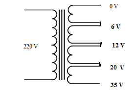
I will buy a custom made 47.5 amps multi tap transformer .of course i will use full wave bridge rectifiers(e.g mda5010) to convert to DC.I want to build a dual channel linear DC power supply 20 Amps each channel.I will switch the taps so there is minimum heat generation i.e use one tap for low DC output voltage and switching to higher voltage tap for higher output DC voltage.
questions:
1) can i get 5 amps between 0 and 6v and 10 amps between 0 and 12v taps?e.g one channel consumes 5v/5amps and the second channel consumes 9v/10amps.
2) should i use isolated taps like the above image
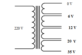
or i should use non isolated taps like the below image?.

3) where is the best position for ground or 0V?.
4) what voltages will be the best to wind the taps for?Remember i will wind the transformer from a local shop.I haven't bought yet.I intend to use the power supply for lab work,charging 12 and 24v lead acid batteries 3.7v lithium ion batteries and testing different things in a typical electronics lab.
5) can i switch the output pass transistors to get 40 amps single channel/20 amps dual channel or will i have to parallel two channels to get 40 amps if each channel is 20 amps or is there any other way of doing it?.
6) what is the upper limit on current that i will need in maximum situations?
7) any ideas for good heat sinking.I have got many small computer power supply fans
8) how much capacitance value should i use per channel?
9) which type of switches will best suit my case to switch the taps?
-
3\$\begingroup\$ It's too many questions in one post Muhammad. Best maybe to focus on first things first, like whether it makes sense for your purposes to build such a big power supply as you suggest. Saying more about your purposes is a good way to start on that count. 40A at 12V is 480 Watts. That's a pretty big power supply. It will take a fair amount of careful design to get something that big to work well. In particular, it will require several pass elements in parallel, assuming you're proposing a linear design. The transformer is probably not where I would start :) \$\endgroup\$– scannyCommented Oct 30, 2015 at 5:10
-
\$\begingroup\$ don't mind it is my first question on this forum.i need to test inverters which do require like 50 amps or so at 12 volts. \$\endgroup\$– Muhammad SaadCommented Oct 30, 2015 at 5:18
-
\$\begingroup\$ To be more clear, what I'm saying is that if you don't focus down your question it's likely to be closed for being too broad :) \$\endgroup\$– scannyCommented Oct 30, 2015 at 5:20
-
1\$\begingroup\$ Why not just charge sealed-lead-acid batteries from a smaller supply? If you're just testing inverters. \$\endgroup\$– rdtscCommented Oct 30, 2015 at 12:06
2 Answers
As I mentioned in my comment, your question is too broad for this format. However, in the interest of moving you forward in your project, I propose the question of: "What kind of power supply should I be thinking of building for this use case?"
A lab power supply is generally of the linear variety (as opposed to a switching power supply). I think the first decision here is whether a linear supply will be feasible for you.
That question comes down immediately to the question of heat dissipation. A linear power supply reduces its output voltage by dissipating the excess energy as heat. Worst case for the specs you mention would be 50A at short circuit, although 50A at 1V would be almost as severe. If your unregulated supply (transformer + rectifier + bulk capacitor) output say 15V, the worst case heat dissipation would be \$15V \times 50A = 750W\$. That's one heck of a big heatsink, even with a noisy set of cooling fans.
So I'd be inclined in your position to strongly consider a switching power supply which would vastly reduce the amount of heat dissipation required.
For that I think you'll need to elaborate your statement of your requirements and perhaps then ask a more specific question addressing the next step for you.
-
1\$\begingroup\$ When you make allowance for the line voltage tolerance and ripple and so-on, these types of supplies, based on rectified AC are really not very practical. They end up requiring way more transformer iron, heat-sinking, giant capacitors, inrush current limiters, etc. I agree the OP should look into switch-mode supplies. \$\endgroup\$ Commented Oct 30, 2015 at 6:02
-
\$\begingroup\$ switching power supplies are noisy so i am considering linear ones.as for the heat dissipation i can ask the transformer maker to wind 11 taps each of 3 volts so that the heat generated will be at most 3V×40A=120W \$\endgroup\$ Commented Oct 30, 2015 at 6:12
-
\$\begingroup\$ The heat is dissipated in the pass elements (perhaps power MOSFETs in your case), not the transformer. It's those devices that need the cooling. The power calculations can't be gotten around by breaking the voltages up. If you put four 3V circuits in series, you still get the ~750W figure, possibly more depending on whether the dropout voltage is once per 3V stage or overall. \$\endgroup\$– scannyCommented Oct 30, 2015 at 6:17
-
2\$\begingroup\$ One trick to mitigate the noise from switching supplies is to use a switcher to get down to a voltage a couple of volts above your target voltage, and then use a LDO regulator to drop down to the exact output voltage required. \$\endgroup\$– tcrosleyCommented Oct 30, 2015 at 7:06
-
\$\begingroup\$ 750W is not a problem for the transformer as it will be designed to handle that much power.If i need like 13 volts DC output i will switch to use 4 taps×3v=12v AC so 12v×1.4-1.4v diode drop=15.4v DC.power wasted=15.4v-13v=2.4v×40A=96W.not a problem \$\endgroup\$ Commented Oct 30, 2015 at 7:15
Transformers are expensive and heavy so I think its best to utilise the transformer to the max .Series/paralell windings are best here so why not have 4 identical secondary windings.You could use some dpdt relays to do this on the sec AC side or if you are keen you could do this on the secDC side.I recommend schottky diodes because they will waste half the voltage of a normal diode which helps minimise the secondary voltage of the transformer you intend to get wound.You still have serious heat to beat so lots of pass transistors .Remember that most cheap power mosfets arnt so happy in analog.So you could use BJTs.If you still want to use mos then use high voltage types with source resistors for paralelling .or better some active current balance or put them in series .
-
\$\begingroup\$ Schottky diodes do have a lower Vf, however they also have a significantly higher leakage current, especially over temperature. See this video for details. \$\endgroup\$– rdtscCommented Oct 30, 2015 at 12:01

