3
\$\begingroup\$

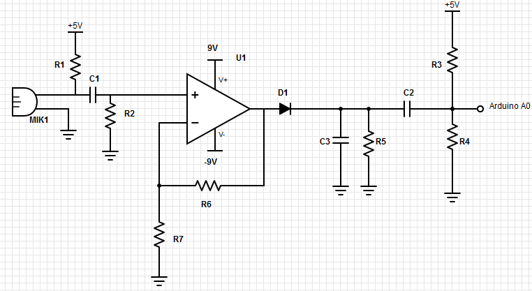
Ok so in the last couple of days I did a lot of research to get everything to work. What I want to do is make a dB sensor with the Arduino. I made the following circuit:

enter image description here

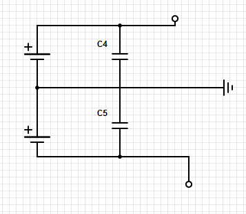
To make the supply voltage for the op-amp U1 I have used the following as power supply:

enter image description here

I have set the values of the first circuit to the following:

  1. R1=2200 ohm (this matches with the internal resistance of the mic)
  2. C1=100nF
  3. R2=38100 (To match the Fcut of 50 Hz)
  4. R6=100k ohm
  5. R7= 1k ohm
  6. R3=r4=1kohm
  7. D1,C3,R5 are currently left out ,because there are some problems earlier on
  8. R3=R4=1kohm , therefore there will be added a offset of 2.5 volts
  9. The op-amp is a lm741
  10. Mic datasheet: http://www.farnell.com/datasheets/1660938.pdf

I have made the amplification of the op-amp 100, because of I wanted the max. value of 2.5 volts to be around that decibel level. The maximum that will be measured is 2.5 volts. The sensitivity of the mic is -41 dB by 94 decibel and that (thanks to andy aka) will/should become 2.5 volts (peak voltage) when measuring.

The big problem is that I only get 200 mV at max (I tested with 90dB-100dB). What could be the problem? Any error in the schematic, please tell me I am really learning a lot right now over this topic!

\$\endgroup\$
7
  • \$\begingroup\$ What was your audio source for the test? How far? Pure sine or did you use music? \$\endgroup\$ Commented Nov 4, 2015 at 7:12
  • \$\begingroup\$ I did use music, but was about 30-50 cm away. It was just some music from YouTube and it was for sure 90dB. I measured that with a real decibel meter from the same distance \$\endgroup\$
    – user90392
    Commented Nov 4, 2015 at 7:25
  • 1
    \$\begingroup\$ Unless you measure on a scope (the peaks) music is not a good test. Music has high crest factor. Use pure sine if you measure with voltmeter. And I trust you're measuring on the AC scale, otherwise it's probably just the DC offset of your opamp... \$\endgroup\$ Commented Nov 4, 2015 at 7:28
  • \$\begingroup\$ OK, i will try that, but if you look at the circuit and the calculation, those seem correct? \$\endgroup\$
    – user90392
    Commented Nov 4, 2015 at 7:30
  • \$\begingroup\$ The circuit looks fine for its purpose. LM741 will hiss a lot if you actually plan to use it as a preamp to record stuff, but just for sound pressure measurements, it should be workable. \$\endgroup\$ Commented Nov 4, 2015 at 7:31

3 Answers 3

1
\$\begingroup\$

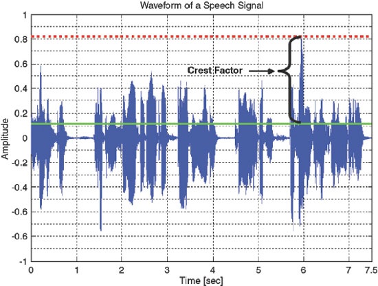
-41 dBV when amplified by 100 has a peak value of 1.26V so your calculations are good but you haven't considered that music is neither 1kHz nor does music have a peak to RMS ratio of 1.414:1 (3dB). The waveform below is speech just to show what you might be up against: -

enter image description here

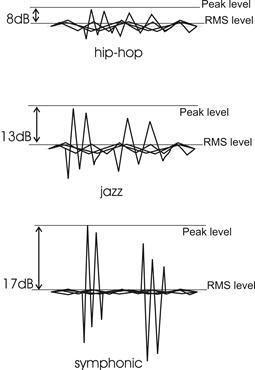
I don't know what type of music you listen to but here's a general guideline for hip-hop versus jazz versus symphonic: -

enter image description here

Music that I mix tends to have a 13 dB crest factor and hip-hop is really compressed (but louder).

The problem arises at high crest factors at an SPL of 94dB (for example) because the peak signal might be 10 dB to 20 dB higher (not the 3dB higher that a sinewave delivers). This peak is likely to bust your ADC input so, what you need to do is protect that input with a zener diode.

Apart from this, C2, R3 and R4 make no sense whatsoever, Take you rectified output and feed it thru a 1k resistor and then to a zener diode that is rated to clip the peaks and prevent your ADC being destroyed.

You might also consider the superior performance of a precision op-amp rectifier. I'll leave you to look that up after getting the more basic circuit working.

\$\endgroup\$
2
\$\begingroup\$

The most likely culprits are R3 and R4, assuming C2 is 100 nF. You've missed the point that, although they produce an offset, they also interact with C2 to form a high-pass filter with a corner frequency of about 3 kHz. Generally, the amplitude of "real" sound drops off at higher frequencies. This is why, for figuring out gain, you need a sine wave generator rather than music. Try replacing R3 and R4 with 10k or 100k resistors, and/or replace C2 with a larger cap.

\$\endgroup\$
1
  • \$\begingroup\$ Good point, when he said he left a bunch of stuff I assumed he left out all the stuff to the right of the opamp. But re-reading his post he didn't leave R3, R4. As for C2, he didn't mention any value... \$\endgroup\$ Commented Nov 4, 2015 at 8:12
-2
\$\begingroup\$

It seems that others seem to have missed the obvious.

D1 acts as a half wave rectifier, which will develop a +ve voltage on C3.

I assume that you want to couple this voltage into the ADC of an Arduino. This DC voltage will be blocked by C2 however.

Remove C2 (and R3, R4) and it may work as intended with the DC voltage following the envelope of the sound intensity.

A somewhat better rectifier can be made by putting the diode 'inside' the feedback loop. Look for examples of precision rectifier circuits.

\$\endgroup\$

Your Answer

By clicking “Post Your Answer”, you agree to our terms of service and acknowledge you have read our privacy policy.