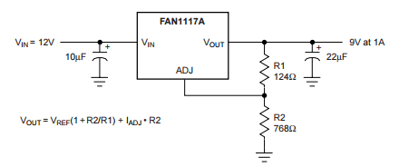
I am really trying to understand how to use adjustable voltage regulators such as the LD1117 sold by sparkfun. I had a look at the datasheet they provide in the product page but it points me to a Fairchild semi conductor datasheet which has a typical application note that looks like this:
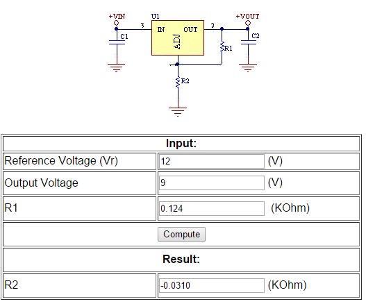
All fair and well so I went over to this online calculator and tried to see how these values work. This is where I suspect I am making a mistake or misunderstand something. See below on how I calculated the values:
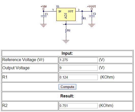
That did not make sense. So I realized that Vr is not related to Vin. I redid the calculation and I think I understand it now.
This looked much better and more inline with what I was excepting. My first challenge was to do a simple 5V to 3.3V conversion as I have done this before with a fixed output regulator.
Then I had a look at the IC close up and well confusion struck me. The IC is marked a ST Electronics LD1117 E439. Now this IC has a datasheet here. This datasheet is a lot more detailed and on page 24 there is an application note for the adjustable variant.
Which one should I use? I did a calculation based on the sparkfun datasheet and I got a value for R2 of 0.174KOhm/174Ohm using the ST datasheet I got very close to this 0.168KOhm/168Ohm.
I am pretty sure I am correct at this point but I hate the blue smoke monster and I just needed a sanity check from a copilot.
One other question with the adjustable voltage regulators the input voltage can range from 15V downwards? I know at some point when the Vin drops too low there will be now conversion but using these values above would I be able to convert say 9V,12V or even 15V to 3.3V?
UPDATE:
So last night I built a PCB using the LD1117. Initially I got an output of 2V... I was stumped. Then I realized I had the two resistor swapped around...duh... facepalm...
Long Story short. I can confirm this works. With the experiment I have just done I am pretty sure I understand this now.


