0
\$\begingroup\$

I'm building a small electronic project that will measure the power consumption of a device and send this back to Arduino or ESP2866.

I've figured out how to measure the current that goes trough a power cable using the ACS712. This works fine.

The only problem I have is sending the input voltage be it either 110 Volt or 230 Volt. The easiest for me to work with would be an output signal of 3.3 Volt. E.g. 0 volt when the input voltage is 110 Volt and 3.3 Volt when the input voltage is 230 Volt.

Then if my input pin is 0 volt (digital 0) AND I measure a current I can assume that the input voltage is 110 volt. If the input pin has 3.3 volt (digital 1) and I measure a current I can assume that the input signal is 230 volt.

Right now I am setting stuff up on a breadboard but when all is done it should have an as small as possible footprint. Around 2.0 x 2.0 centimeters.

Anybody has some good tips on how to do the voltage sensing?

\$\endgroup\$
4
  • \$\begingroup\$ Maybe something like the line voltage deviation circuit in this application note? \$\endgroup\$
    – Arsenal
    Commented Nov 20, 2015 at 14:59
  • \$\begingroup\$ How fancy do you want this to be...in other words, how many parts/ $$ are you willing to spend in order to make it good? You could do this with just a resistive voltage divider directly on the mains, but it's not necessarily the best idea... \$\endgroup\$ Commented Nov 20, 2015 at 15:08
  • \$\begingroup\$ Footprint should be low so a "huge" components like transformer is not an option.I open open to ideas.The voltage deviation that @Arsenal mentioned is also an idea that I will look into. I am not sure how I could detect voltage with a resistive voltage divider, got a schematic? \$\endgroup\$ Commented Nov 20, 2015 at 16:13
  • \$\begingroup\$ Have you thought about using a proper energy measurement IC like AD7751? \$\endgroup\$ Commented Nov 20, 2015 at 20:50

2 Answers 2

1
\$\begingroup\$

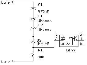
Use an opto isolator fed from the ac via zener diodes. Below a certain ac voltage the zeners will block the ac voltage. Zeners need to be wired in series anode to anode to properly handle the ac. Same technique used in an analogue phone to prevent audio levels triggering the ringer circuit: -

enter image description here

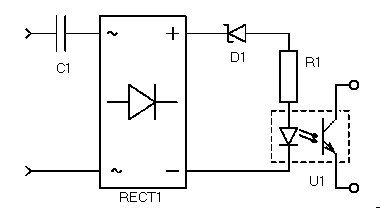
Probably rate the zeners at 180V to 200V stand-off voltage i.e. sufficnent to block the 170V peak voltage of 120V AC RMS. Here's one that uses a bridge and one zener: -

enter image description here

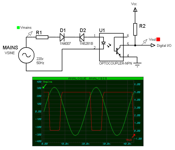
Here's another slight variation: -

enter image description here

The 1N5281 is a 200V device but I'd probably put a revers diode across the opto input to be safe. You can see in the scope picture that the opto output goes low with around 200V at the input.

Non of these circuits provide a definite on/off signal - they will all pulse as the waveform exceeds around 200V but converting that signal to a constant high/low signal is really trivial.

\$\endgroup\$
3
\$\begingroup\$

First, be careful when you're dealing with mains.

Please refer to this question for why breadboards and mains power don't mix (the question relates to 120V, 230V is worse).

As far as measuring the difference between 110V and 230V, there are a few methods. For safety, all methods should be properly isolated when dealing with mains power.

  1. Use an ADC and a resistor divider. In a micro, just keep track of the most recent peak voltage - since you know the ratio, you can tell if you're plugged in to 110 or 230V.
  2. Use a transformer to knock the voltage down to something you can actually read on an ADC. Combine this with a resistor divider, and you have an isolated, relatively safe way to measure the voltage.
  3. You can also combine (2) with some kind of fixed voltage reference and a comparator. If your reference is somewhere between what 110v and 230v yields on the output of your transformer, then you will get a logic high if the input is 230v, and a logic low if it is 110v.

Seriously though - be careful with mains power. Always keep everything isolated, and be very careful what you touch.

\$\endgroup\$
2
  • \$\begingroup\$ Thanks your feedback and reminding me on the breadboard and main power warning! Do you maybe have a link to a schematic/article regarding the first solution? \$\endgroup\$ Commented Nov 20, 2015 at 16:03
  • 1
    \$\begingroup\$ Here is a link to a forum post on eevblog discussing the various possibilities (with some schematics): eevblog.com/forum/beginners/mians-resistor-divider \$\endgroup\$
    – Ken
    Commented Nov 20, 2015 at 16:10

Your Answer

By clicking “Post Your Answer”, you agree to our terms of service and acknowledge you have read our privacy policy.

Not the answer you're looking for? Browse other questions tagged or ask your own question.