2
\$\begingroup\$

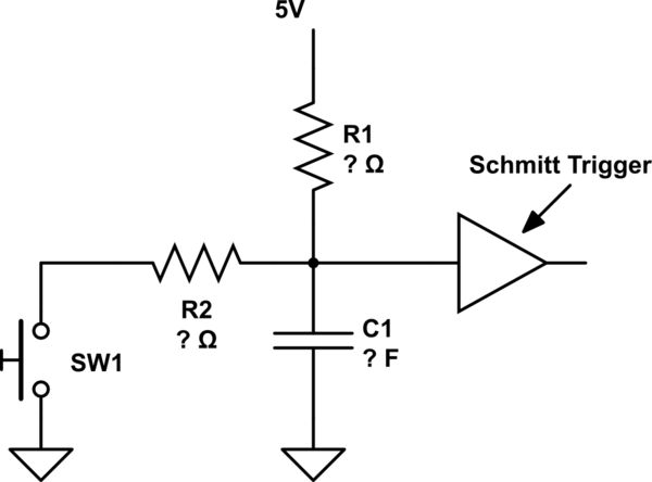
I'm newish to electronics and I am trying to make a circuit that charges a capacitor, then discharges it when a switch is closed. The signal then goes into a schmitt trigger to be cleaned up. The trigger I was thinking of getting is this

schematic

simulate this circuit – Schematic created using CircuitLab

My question is will this circuit work or have I screwed it up? Also how to I figure out the correct values of the capacitor and resistors? I want the capacitor to charge in around 20ms if that is possible. Thanks

\$\endgroup\$
2
  • 1
    \$\begingroup\$ And how quickly do you want it to discharge? \$\endgroup\$ Commented Nov 23, 2015 at 0:13
  • \$\begingroup\$ As quickly as possible when the switch is closed, I don't know how quick you can get them \$\endgroup\$
    – oodan123
    Commented Nov 23, 2015 at 0:14

4 Answers 4

1
\$\begingroup\$

That'll work.

Assuming you want 'reasonable' values, choose R1 somewhere between 1k and 100 kohm. Choose C so that 0.7*R1*C is the time you need. Choose R2 << R1, but at least 10 ohm (to protect the switch from arcing when you use it to discharge the capacitor.

So to charge in 10 seconds (consider that a long time), choose R1 = 100k. Then C is (10/70k) = 150 uF.

Note that capacitors are not particularly accurate (neither is the schmitt trigger), so your results may vary. It's easier to modify R1 to adjust.

\$\endgroup\$
3
  • \$\begingroup\$ Thanks for that, where does the 0.7 come from? \$\endgroup\$
    – oodan123
    Commented Nov 23, 2015 at 0:26
  • \$\begingroup\$ And just to confirm, if I use a 10k resistor for R1 and I want the capacitor to charge in 20ms, I should get around a 28uF capacitor? (0.2/7000) = 28uF \$\endgroup\$
    – oodan123
    Commented Nov 23, 2015 at 0:34
  • \$\begingroup\$ sorry 0.02/7000 = 2.8uF \$\endgroup\$
    – oodan123
    Commented Nov 23, 2015 at 1:05
2
\$\begingroup\$

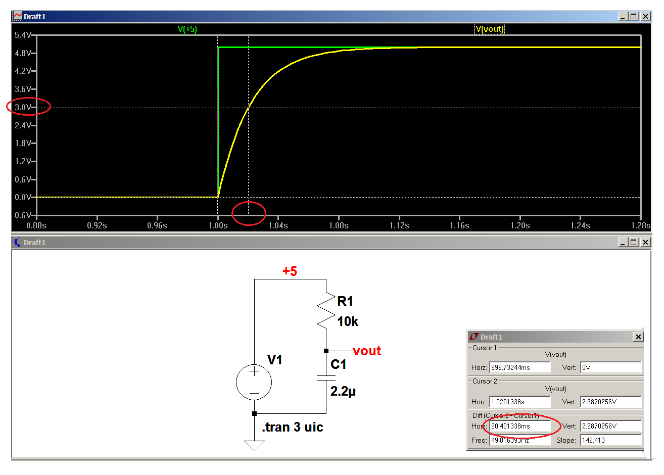
Since a Schmitt trigger exhibits hysteresis on its input, let's say - just for the purpose at hand - that the high trigger point (Vt+) is 3 volts and the low trigger point (Vt-) is 2 volts with Vcc equal to 5 volts.

Then, when Vcc first comes on, we'll want the cap to charge up to Vt+ in 20 milliseconds, and when the switch is made we'll want the cap to discharge to Vt- as quickly as possible; let's say 2 microseconds.

The charge time of the cap is given by:

$$\text t = \text {kRC}$$

Where t is the charge time in seconds, R is the resistance in ohms, C is the capacitance in Farads, and

$$\text{k = ln}\ \ \frac{\text {Vcc}}{\text {Vcc-Vt+}} = \text{ ln}\ \ \frac{\text {5V}}{\text {2V}} =\text {0.92} $$

Then, arbitrarily choosing 10k\$\Omega\$ for R and rearranging to solve for C, we have:

$$\text C = \frac{\text t}{\text {kR}} =\frac{\text {20ms}}{\text {0.92}\times{\text{10k}}\Omega} = \text {2.2 microfarads} $$

This is borne out by:
enter image description here

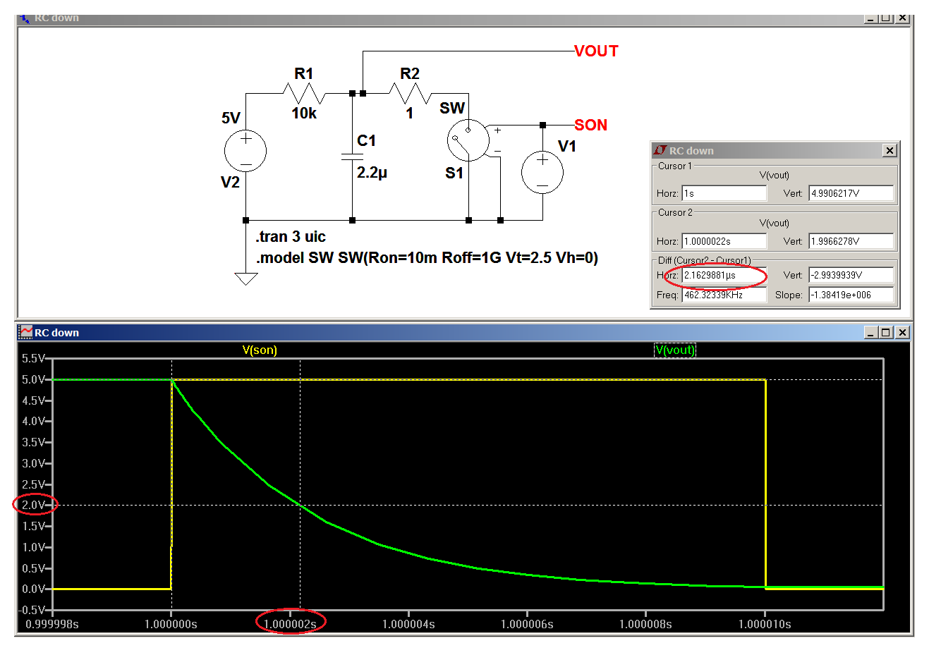
Now, if we let the cap sit for a while it'll charge up close enough to 5 volts to call it 5 volts, and now what we want to do is discharge it to 2 volts in 2 microseconds.

Then, since we have 5 volts across the cap and we want to discharge it by 3 volts, "k" stays the same and we can write:

$$\text R = \frac{\text t}{\text {kC}} =\frac{\text {2} \mu \text{s}}{\text {0.92}\times\text{2.2}\mu \text{F}} \approx \text {1 ohm} $$

The current out of R1 is dropping a little voltage across R2, which is keeping C1 from discharging as quickly as it could if that current wasn't there, and, if it matters, R1 could be made larger and C1 smaller, or the value of R2 could be fiddled with.
enter image description here

\$\endgroup\$
0
\$\begingroup\$

R1 x C1 form the time constant, which means after one time constant, the voltage across C1 is 0.63 times 5V, or 3.15V. So you can pick an R1 and calculate C1 using 20msec / R1.

If R1 = 1000 ohms, then C1 = 0.020sec / 1000ohm = 0.00002 Farads or 20 uF. If R1 = 10Kohms, then C1 would equal 2uF.

Make sure you check the voltage that the Schmitt trigger switches on the positive going edge. Usually it will be slightly higher than mid supply voltage.

\$\endgroup\$
0
0
\$\begingroup\$

The basic capacitor charging for an RC circuit is (0.63 x Vdiff) in each RC time.

So for example if the RC product came out to 1 the capacitor would charge up to (0.63 x 5V) = 3.15V in one time constant (or 1 second). Then during the next RC time constant the capacitor charges the same 0.63x of the remaining difference (Vdiff). See: https://en.wikipedia.org/wiki/RC_time_constant

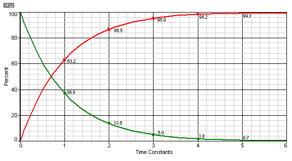
To fully charge the capacitor to 5v (when starting from 0V) it takes approximately 5 x RC. So to get a a 20ms charge to 5V you need an RC product of (20ms/5) = 4ms. Values of C=1uF and R=4k would do well.

EDIT: For the best reference see the capacitor charge/discharge chart below. This is how the capacitor voltage changes during each RC time period. Note that the first RC time corresponds to the 63% voltage change point, and after 5 time periods the voltage change is nearly constant (as fully charged or fully discharged).

enter image description here

\$\endgroup\$
6
  • \$\begingroup\$ And a 100 ohm resistor for R2 would work fine? \$\endgroup\$
    – oodan123
    Commented Nov 23, 2015 at 1:20
  • \$\begingroup\$ Note: I am assuming you wanted to charge up the capacitor to the full 5V. A few of the other answers are giving you a charge up to only 3.15V, (1xRC). While that may be enough to flip the logic gate, you didn't really state what was needed here \$\endgroup\$
    – Nedd
    Commented Nov 23, 2015 at 1:21
  • \$\begingroup\$ Yes I intend to flip a logic gate \$\endgroup\$
    – oodan123
    Commented Nov 23, 2015 at 1:23
  • \$\begingroup\$ Actually, you are not likely to even notice the time difference of 20ms to 100ms for the capacitor charging. I assume you really wanted to have the "discharge" time carefully set, (in your question you listed "charge in around 20ms"). The discharge curve is just the inverse of the charge curve. So R2 x C1 will be the time constant. However the lowest capacitor voltage will be (5v/(R1+R2))xR2. This is why the R values listed by jp314 are shown as very far apart. So in general R1 needs to be the much higher value, thus the charge time is always very slow. \$\endgroup\$
    – Nedd
    Commented Nov 23, 2015 at 1:44
  • \$\begingroup\$ That makes sense \$\endgroup\$
    – oodan123
    Commented Nov 23, 2015 at 2:21

Your Answer

By clicking “Post Your Answer”, you agree to our terms of service and acknowledge you have read our privacy policy.

Not the answer you're looking for? Browse other questions tagged or ask your own question.