0
\$\begingroup\$

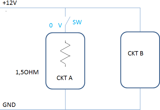
enter image description hereI am designing this circuit for testing purpose to test the following conditions.

1.When +12V is applied to the test circuit,my Circuit B should be activated for 2ms and trip open.CKT B is already designed and working fine.During this condition,my CKT A should be inactive. 2.When no power is applied ,my CKT A should be activated.

I am using Normally closed relay in the place of switch(SW), so that my CKT A is always on and inactive when +12V is applied.The minimum response time of the relay I found was approximately 0.5ms.I want to reduce this response time as it will have an impact on CKT B activation time.

Is there any option to use any other switching device to satisfy this condition.

\$\endgroup\$
8
  • \$\begingroup\$ FETs will work much faster than relays, but it is not clear what exactly you want. What generates the 2 ms right now ? \$\endgroup\$
    – jp314
    Commented Nov 27, 2015 at 22:14
  • \$\begingroup\$ How much current does circuit A draw when its active and how much "extra" resistance can be tolerated in series with circuit A before it fails to perform as you would want? \$\endgroup\$
    – Andy aka
    Commented Nov 27, 2015 at 22:25
  • \$\begingroup\$ Mechanical relay will be far too slow. \$\endgroup\$
    – Autistic
    Commented Nov 28, 2015 at 1:07
  • \$\begingroup\$ @Andyaka: Basically I want my ckt A to be active when there is no +12V applied.Circuit A draw current of 10-20mA from constant current source to measure the resistance. \$\endgroup\$
    – Newbie
    Commented Nov 29, 2015 at 7:21
  • \$\begingroup\$ You said that Ckt A draws 10-20 ma. If it is only on when +12v is off (i.e. normally closed NC contact), where is the current source for Ckt A coming from (since you have it connected to the +12V line and nothing else)? Seems like Ckt A is never really connected to +12V but something else. Is there more to the circuit than you are showing? \$\endgroup\$
    – tcrosley
    Commented Nov 29, 2015 at 16:36

1 Answer 1

2
\$\begingroup\$

I don't think you need solid state relays and such; they are terribly expensive, at least $35 to get one with a low on-state resistance, and the best turn on/turn off times are in the order of 50-100 µs, not all that better than what you are using now. Instead, you should be able to just use a N-channel FET as a low-side switch. The IPB009N03L has a very low R\$_{DS(on)max}\$ of 0.95 mΩ, a turn-on delay + rise time of 50 ns, and a turn off delay + fall time of 125 ns. It is designed to work with a logic level input since it has a minimum V\$_{GS}\$ of 2.2V. It is available at Digi-Key for $2.87.

The main disadvantage of a low-side switch is the switched circuit is no longer connected directly to ground. However with such a low R\$_{DS(on)max}\$, and currents under 20 mA, it shouldn't matter.

But if you must use a high-side switch, you could use the P-channel IPB180P04P4L-02. It also has a low R\$_{DS(on)max}\$ of 2.4 mΩ, a turn-on delay + rise time of 50 ns, and a turn off delay + fall time of 265 ns. It has a minimum V\$_{GS}\$ of -2.2V. It is available at Digi-Key for $2.20.

\$\endgroup\$

Your Answer

By clicking “Post Your Answer”, you agree to our terms of service and acknowledge you have read our privacy policy.

Not the answer you're looking for? Browse other questions tagged or ask your own question.