2
\$\begingroup\$

I am actually a software engineer and not really familiar with wiring. I've been playing around with a Raspberry Pi Model B, and am looking to hook up a 2 PRONG Extension Cable to a Sainsmart 8 Channel Solid State Relay.

I am driving the GPIO pins from RPIO (Python). What I want to do is hook up a basic night light as the first channel output from the SSR and control it from GPIO pin 17. The problem is, I can't even get this to work. I am able to get the LED to light up pretty easily, but there seems to be no output. I've tried driving the relay on a HIGH and LOW signal, but no dice.

My wiring diagram is shown below... Apologies for it being very rudimentary... Any ideas what may be wrong? Is my relay bad?

Also note, I've several mechanical relays too and they all seem to do the same thing.

Also, I've been told that the GROUND side of a 2 PRONG cable is the side where the insulation has labeling. I'm assuming the GROUND part of the 2 prong cable is plugged into the top part of the output channel of the relay and VCC on the bottom. Can someone confirm with me?

I've also tried this with an Arduino, and it doesn't seem to work either. Sorry for the convoluted post, but this has been driving me nuts for the past couple of weeks!

EDIT: The LED on the board does turn on, but I haven't had luck powering something separate off from the port. And yes, I have tried powering it from a separate 5V supply.

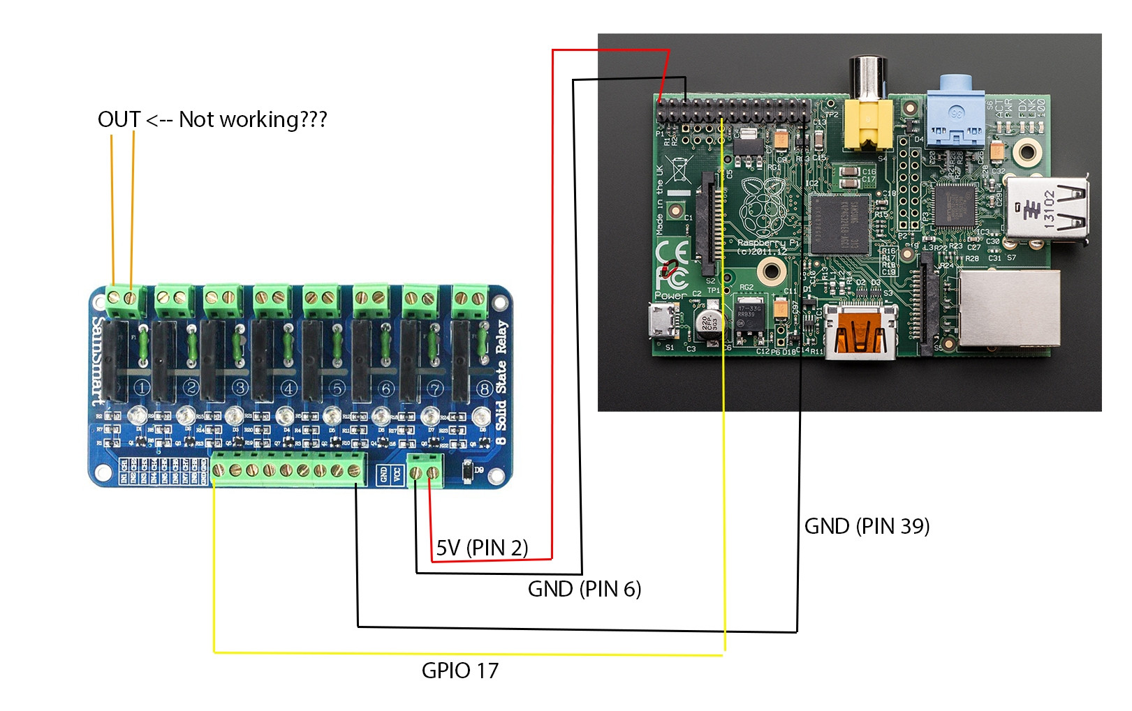
enter image description here

\$\endgroup\$
2
  • \$\begingroup\$ You would need to connect AC voltage and load on output. SSR acts like a switch, imagine that output socket as simple switch for AC voltage only. \$\endgroup\$ Commented Dec 4, 2015 at 9:05
  • \$\begingroup\$ try moving the yellow GPIO wire to pin 1 +3.3V, if that doesn't turn the relay on there's a problem with the relay board, if it does turn it on you may be using the wrong GPIO in your software. + and 2 models of rasapberry pi have different GPIO layout to the original, (where 256K and 512K had different layouts). but using a GPIO library like wiringpi should correct for this automatically. \$\endgroup\$ Commented Dec 6, 2015 at 20:27

3 Answers 3

2
\$\begingroup\$

This is very old now but I keep getting the link in search results so I thought I would comment in case it helps anyone else reading this as I am.

In the original diagram it looks like the questioner is thinking that the 2 pins of the relay that his wire is attached to provide current and ground to run a light. They Don't ... Its just a switch so you hook the hot wire of a light to one side and hook that same wire to the other side of the relay. When the relay is powered it switches the switch on and the current can flow thru the relay just as if it were a light switch. Terrible drawing coming :)

Ground-plug-on-cord------is optional ------------Ground of light/ appliance

Common- plug-on cord ----------------------------Common (usually white) light

Hot wire -----one side of relay---- other end of hot wire to other side of relay

So in my case I did this: Took my light and carefully cut just the black wire and left the green and white wires connected as they were. Then I hooked one end of the black wire to one of the terminals on the relay and the other end of the black wire to the other terminal of the same relay. Then I plugged the power cord into an outlet. When the relay is closed power flows to the light and it lights (if the light switch is on obviously) when the relay is open no current can flow and ther is no power to the light.

Its not the relay that is supplying power to the light. That comes from the wall outlet. The relay is just enabling or disabling power from flowing thru the black wire by connecting or disrupting the path for electricity to flow.

YMMV Be careful when working with AC power.

But switching AC power with a SainSmart relay and a raspberry pi is quite straightforward once you understand a little about it.

\$\endgroup\$
1
\$\begingroup\$

At first glance it looks fine.

Generally for wire two joined conductors the ground will have a stripe running on it. I've seen actual text specifying the wire's specifications on both sides.

Does the LED on the board turn on, or does your statement just mean that you were able to power a separate LED from that port?

You also mentioned you had driven some mechanical relays from that I/O port. What was the coil current for those? It's possible the port could have been damaged it it was overdrawn.

Have you tried other channels on the board, or powering it from a separate 5V supply?

\$\endgroup\$
2
  • \$\begingroup\$ Hi, the LED on the board does turn on, but I haven't had luck powering something separate off from the port. And yes, I have tried powering it from a separate 5V supply. \$\endgroup\$ Commented Dec 4, 2015 at 14:13
  • \$\begingroup\$ Ok, well as @urbanspr1nter mentioned you need a certain voltage for it to conduct, although looking at the datasheet it's 75V minimum. You mentioned you tried a set of christmas lights...maybe a light bulb? Also did you try using a different channel? \$\endgroup\$ Commented Dec 5, 2015 at 17:44
1
\$\begingroup\$

That relay board is only good for switching AC loads of 100V or more. If you have a lower voltage load, it's not going to work.

For low voltage loads use transistors, MOSFETs or a ULN2803 driver board.

\$\endgroup\$
2
  • \$\begingroup\$ I have also tried powering a strand of Christmas lights, but I am not getting anything. :( \$\endgroup\$ Commented Dec 4, 2015 at 14:14
  • \$\begingroup\$ try movifng the pi end of the the vellow wire to pin 1 \$\endgroup\$ Commented Dec 6, 2015 at 20:12

Your Answer

By clicking “Post Your Answer”, you agree to our terms of service and acknowledge you have read our privacy policy.

Not the answer you're looking for? Browse other questions tagged or ask your own question.