0
\$\begingroup\$

I have a circuit where 3.3V are used for MCU and other peripherals, but microswitches are running on 12V. In the first version, microswitch was connected to the base via base resistor of a BJT. What I realized is that the process of switching was producing spikes in the near lines, high enough to trigger my external interrupt of the MCU. I have never seen something like that in practice. So i decided to put rc filter between microswitch and base of BJT. First try has shown that spikes are gone in the near lines. The circuit is shown below.
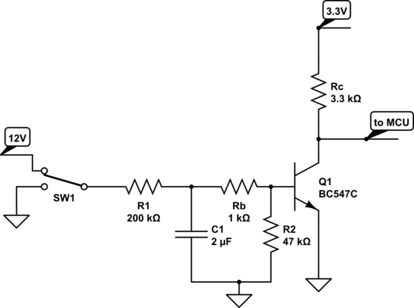
schematic

simulate this circuit – Schematic created using CircuitLab

The idea is to have debounce circuit to prevent input of microcontroller swing for the firs 20ms of the swich vibrations, plus to filter out spikes.

Now, a friend of mine, warns me that 200k ohms in the base circuit is too much, and that one should be aware of such a high impedances in base circuit, cause every induced voltage between Rb and R1 could go to the base, since to the left is 200k. Before I ask my question I wanted to say that I want to have interface between microswitch and MCU via transistor, and I will not consider divider solution.

My questions are: Should I move debouncing between collector and MCU, and use RC filter with smaller time constant in the base in order to remove spikes?

Could you please explain a bit more why high impedances in base circuit are possible problem, as well as all points of high impedance in one circuit.

Whar are possible problems with this circuit?

Cheers

\$\endgroup\$
1
  • \$\begingroup\$ That is a cool sounding project, but you should edit your question to just be your question rather than a project log! \$\endgroup\$
    – Daniel
    Commented Dec 4, 2015 at 16:47

1 Answer 1

1
\$\begingroup\$

You don't need a transistor to do the de-glitch; just use a potential divider to pot down 12v to something like 3V. A 4:1 divider will work using a 1Mohm and a 330k resistor (attenuation converts 12V to 2.98 volts). Then put a 1 uF (or 2uF) across the 330k.

If there's any possibility that the 12V is higher maybe have a protection diode to Vss from the resistor junction. If you have a regulated 12V then all should be fine.

\$\endgroup\$
3
  • \$\begingroup\$ I feel more isolated somehow with transistor. Simple divider would ruin the "purity" of my board. So, let's say this circuit must be preserved. \$\endgroup\$
    – Nexy_sm
    Commented Dec 4, 2015 at 22:00
  • \$\begingroup\$ and, mu question was how to improve this circuit and what is the problem with points of high impedance. \$\endgroup\$
    – Nexy_sm
    Commented Dec 4, 2015 at 22:06
  • 1
    \$\begingroup\$ OK, the base to emitter is not a point of high impedance - your friend is misleading you OR you haven't justified what he told you. \$\endgroup\$
    – Andy aka
    Commented Dec 4, 2015 at 22:58

Your Answer

By clicking “Post Your Answer”, you agree to our terms of service and acknowledge you have read our privacy policy.

Not the answer you're looking for? Browse other questions tagged or ask your own question.