0
\$\begingroup\$

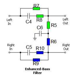
I've built a "Bass Enhanced Crossfeed" from a kit, which I believe is based on Meier's Crossfeed design.

Image from PDF Instructions

I prototyped it first on a breadboard, forgot to ground the output jack because it wasn't explicitly in the diagram. It sounded terrible. After I grounded, it seemed to sound pretty good! So I built the 'hi' version.

Now that I've built it, the low range just seems very subdued compared to my previous test. I suspect I didn't solder it correctly, though I've looked over it with a magnifying glass.

So, how can I verify the build without an oscilloscope and just a multimeter?

I've done some checking, like checking for shorts between left and right ... where are the useful points to check for the right value of resistance? Between R/Lin and R/Lout? Should that be R9/7? Should I check the resistance between each leg of each capacitor?

Probably overkill, but could I put this into a simulator and see what the simulated values would be vs. actual?

Apologies.. I'm a software guy. I'd write unit tests if I could!

\$\endgroup\$
3
  • \$\begingroup\$ I've simulated this circuit many times, it's of course possible. In LTspice you can even feed audio samples through a simulated circuit and output it as an audio sample. electrostud.wikia.com/wiki/Using_WAVE_files_as_input/… \$\endgroup\$
    – pipe
    Commented Dec 17, 2015 at 1:24
  • \$\begingroup\$ Oh, and you can't connect a headphone to this. It will load everything down and affect the frequency response. Not sure if it will be better or worse, but it's not supposed to be used like that anyway. \$\endgroup\$
    – pipe
    Commented Dec 17, 2015 at 1:27
  • \$\begingroup\$ Yes, I discovered that after I built it -- it's supposed to be pre-amp. I have an FiiO E17K I'm connecting it to (pre, not post) \$\endgroup\$
    – rrauenza
    Commented Dec 17, 2015 at 16:27

1 Answer 1

1
\$\begingroup\$

The resistance between Rin and Lin will be R5 + R6 + R7 + R9

The resistance between Rout and Lout will be R5 + R6

The resistance between either input and its output will be R7 or R9 (which I'd expect to be the same)

\$\endgroup\$
2
  • \$\begingroup\$ Thanks for breaking it down!! -- I can't visualize the output and Ground path -- I think of C6 as an airgap. What does it mean to measure resistance to ground when ground is separated by a capacitor? \$\endgroup\$
    – rrauenza
    Commented Dec 17, 2015 at 0:57
  • \$\begingroup\$ Oops - I missed C6 when describing resistance out->ground. Because of C6, the resistance from either output or input to ground will be infinite. \$\endgroup\$ Commented Dec 17, 2015 at 1:07

Your Answer

By clicking “Post Your Answer”, you agree to our terms of service and acknowledge you have read our privacy policy.

Not the answer you're looking for? Browse other questions tagged or ask your own question.