0
\$\begingroup\$

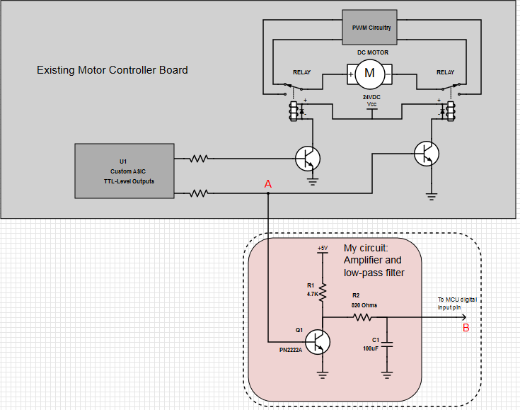
I am working with a motor control board which controls a DC motor (speed and direction). This board uses two SPDT relays for direction, and some sort of PWM for speed.

Here's an abbreviated schematic, including my own circuit.

enter image description here

I need to feed the motor direction to a MCU using TTL levels.

I tapped the circuit at point "A", which outputs 0V when relay is not energized and 0.8V when energized. This corresponds with the motor directions.

I amplified this signal to TTL levels using the circuit shown.

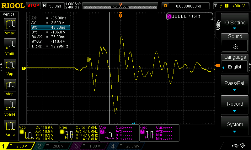
This works perfectly, except when the motor is running slowly (heavy PWM applied to motor outputs). In this state there are repeated spikes at point A and B (see this example) which cause the MCU to think the pin has changed state.

Screen grab of voltage a point A.

You can see the low-pass filter intended to attenuate anything above 2 Hz. But it doesn't filter these spikes for some reason.

Does anyone have any suggestions for cleaning up this signal?

The controller and my circuit share a common ground.

Thank you for any advice!

\$\endgroup\$
6
  • 1
    \$\begingroup\$ I suspect the problem is with the grounding between the driver and your circuit. You should check this carefully. If at all possible reference your circuit's ground to a point on the driver board's SMD circuitry. Otherwise you'll need to use a differential amplifier. \$\endgroup\$
    – Jon
    Commented Dec 17, 2015 at 23:01
  • \$\begingroup\$ Your main problem to receiving answers is too many words. For instance you said "I need to input this information to a single binary digital pin on a standalone microcontroller" and, in reality you mean "This should feed an MCU". I'm saying all of this with your interest at heart because this question reads like a really long story and I gave up after the quote. Maybe others have done the same. No need to apologize etc... \$\endgroup\$
    – Andy aka
    Commented Dec 17, 2015 at 23:40
  • \$\begingroup\$ Thanks Jon. I made sure they were grounded together. I tested using the driver's 5v supply into the amp, then tested with the amp powered from the MCU supply... Same results. \$\endgroup\$ Commented Dec 18, 2015 at 0:44
  • \$\begingroup\$ @Andyaka, I appreciate your honest critique. I have read so many questions on this forum where the submitter is criticized for being too brief or failed to supply enough info. Also I have seen a lot of criticism when something is not worded clearly, so I think this caused me to overdo the explanation. I will try to reword it... \$\endgroup\$ Commented Dec 18, 2015 at 0:46
  • \$\begingroup\$ @Andyaka, is it better now? \$\endgroup\$ Commented Dec 18, 2015 at 0:58

3 Answers 3

2
\$\begingroup\$

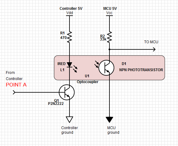
So I solved the problem. I built an opto-isolator using an IRED and phototransistor and some black tubing. This effectively eliminates the EMI and gives me a clean square wave. Note that some applications may require a resistor on the base of Q1, but in this application the resistor is already present on the control board as shown in the previous schematic.

For the phototransistor I used some left-over GE L14GX536 parts in my bin.

Here's a schematic of the final product, in case it's helpful to someone: opto-isolator

\$\endgroup\$
0
1
\$\begingroup\$

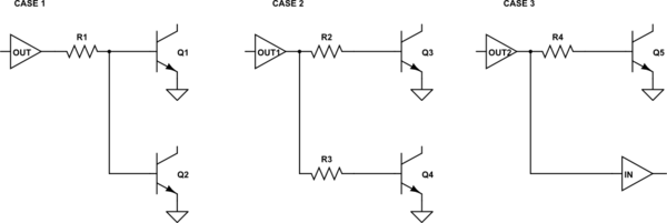
Is the problem related to sharing the base resistor between two transistors?

schematic

simulate this circuit – Schematic created using CircuitLab

Case 1 shows your present configuration. Is it possible that one transistor hogs the base current under certain circumstances causing unreliable switching of Q2?

Case 2 shows independent base drive for each transistor. This should be more reliable.

Case 3 is just checking the obvious: Why not take the control board directly to the MCU? I presume the answer is that it's not TTL output levels.

\$\endgroup\$
5
  • \$\begingroup\$ Yes it is TTL level, but the MCU is a SMD chip and the resistor is very close to the pin - not much room to solder. I just picked point 'A' because it was a pre-existing via, and easy to solder a wire there. \$\endgroup\$ Commented Dec 18, 2015 at 1:46
  • \$\begingroup\$ Still get the spikes (snag.gy/QjfeS.jpg) even when tapping from the point suggested in Case #3. Used RC filter but no luck... I'm confused. \$\endgroup\$ Commented Dec 18, 2015 at 2:26
  • \$\begingroup\$ Time for a photo, I think. Show us the updated 'scope grab too. You should update the images to imgur via the editor. The links are less likely to break. Show them inline too - I have to open three tabs to read your question. \$\endgroup\$
    – Transistor
    Commented Dec 18, 2015 at 10:15
  • \$\begingroup\$ I will try to upload photos asap. As an update, I'm seeing the spikes on the 5V rail of the controller also! It's not just appearing on the signal line. So it appears to be noise from the motor... ? your thoughts? \$\endgroup\$ Commented Dec 18, 2015 at 16:19
  • \$\begingroup\$ I'm thinking optical isolation would be a better route... your thoughts? \$\endgroup\$ Commented Dec 18, 2015 at 16:27
0
\$\begingroup\$

Tapping the signal at point "A" was probably motivated by the idea of protecting the ASIC (U1) from possible damage. But it says, "TTL-Level Outputs". So it's very likely that output could connect directly to the MCU.

If you still want to be cautious, move point "A" to the other side of the resistor, and add another series resistor to drive your transistor, Q1. This provides a better drive signal to Q1. Doing it the way you show essentially tries to drive two transistors in parallel, each of which is going to try to limit the "high" state voltage to (as you observed) 0.8 volts. They would be sharing the input current from the single resistor.

One more thing. Because of the transistor's gain, or change in impedance going from input to output, it's much harder to filter the signal at the output. Filtering the input (at the base of Q1) would require a smaller capacitor. The impedance is higher because of the decoupling from the input resistor. Probably with the changed drive setup, you won't need any filtering...assuming there isn't any PWM present on that direction signal from U1.

\$\endgroup\$
4
  • \$\begingroup\$ Hi gbarry, I could do that, but the soldering is very delicate because it's a SMD ASIC, and the resistor is very close to the pin. So there's not much room to solder. So I was trying to avoid it since there was a perfect place to tap at point 'A'. \$\endgroup\$ Commented Dec 18, 2015 at 1:44
  • \$\begingroup\$ Also you're correct: no PWM on this signal. \$\endgroup\$ Commented Dec 18, 2015 at 1:45
  • \$\begingroup\$ I tried tapping from the point above the resistor like you and @transistor suggested. However I still get the spikes, even when using the RC filter: snag.gy/QjfeS.jpg \$\endgroup\$ Commented Dec 18, 2015 at 2:25
  • \$\begingroup\$ I'm thinking I should use optical isolation between the controller board and my mcu. Going to try that next and see what happens. \$\endgroup\$ Commented Dec 18, 2015 at 16:23

Your Answer

By clicking “Post Your Answer”, you agree to our terms of service and acknowledge you have read our privacy policy.

Not the answer you're looking for? Browse other questions tagged or ask your own question.