I have always been told that LEDs need a resistor in series when powered from a battery.
If this is true, how is it possible to power an LED from a coin cell battery without a resistor? I have tried this, and it works without burning out the LED.
I have always been told that LEDs need a resistor in series when powered from a battery.
If this is true, how is it possible to power an LED from a coin cell battery without a resistor? I have tried this, and it works without burning out the LED.
No battery is an ideal voltage source. This is easy to demonstrate: measure the voltage of a coin cell battery with a voltmeter. For your typical lithium coin cell, it should be around 3V. Now connect the LED to it, and measure the voltage again. The voltage should be around the forward voltage of the LED.
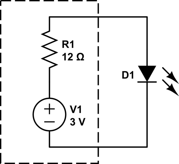
This works because real batteries have some internal resistance. A fresh coin cell might be approximately modelled by adding a series resistor. With an LED connected, it might look something like this:

simulate this circuit – Schematic created using CircuitLab
It's the internal resistance of the battery, R1 here, which limits the current. Just like a discrete resistor, this internal resistance drops a voltage proportional to the current through it according to Ohm's law. It also makes the battery warm.
The internal resistance also increases significantly as the battery discharges, and this is why a fresh alkaline battery might measure 1.65V, whereas a dead one might still measure 1.4V, but is unable to provide enough current to work as intended.
There's another way to demonstrate a battery's internal resistance: short a coin cell's terminals with a wire and note that it does not explode. The internal resistance of the battery limits the current through the wire (which has nearly zero resistance), and thus, limits the rate at which electrical energy is converted to heat.
Now try the same experiment with a lithium ion battery (which has a very low internal resistance) and a heavy gauge wire (which also has a very low resistance) and you will create a sizable explosion, or at least a fire.
On second thought, don't try that second experiment.
That's because your battery is a voltage source and a resistor at the same time.
This... became a bit longer, but it nicely describes how LEDs and resistors work together without any math...
Have a look at the violet curve of this plot, and ignore the rest for a moment.
The curve sketches (i.e. the slope is just a number chosen by me, not real data) the voltage-current-characteristic of an LED with a nominal current of 20mA at 3.2V.
Now, consider the green curve, which could be another LED of the same type with some part spread, or even the same LED at higher temperature.
So, if the nominal LED voltage is above the source voltage, you don't need a resistor. But make sure this is still valid in worst cases where the LED will sink 20mA at a lower voltage.
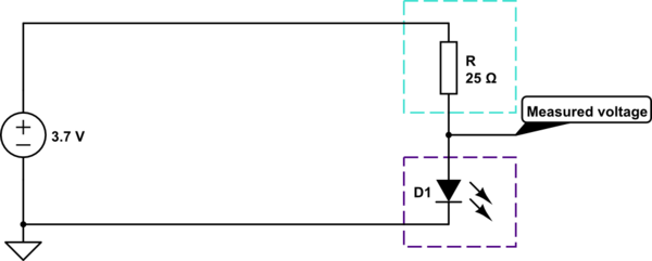
Now, let's think about a higher source voltage of 3.7V and a resistor of 25Ohm, which is perfect for the LED:

simulate this circuit – Schematic created using CircuitLab
Let's play an intellectual game: Replace the LED by a potentiometer, and turn it. The voltage and current measured at the indicated node are drawn as blue line in my diagram above. (You can keep the LED and replace the resistor to get the violet/green curve, too)
The working point is where the blue line crosses the curve of the LED, since there current and voltage are the same for both games.
Now, the working point of the "bad" LED is about 3.16V and 23mA, which should still be fine.
Now, a coin cell usually has a nominal voltage of 3.0V, though you can usually measure 3.1V when it's full. Most bright LEDs have a nominal voltage of 3.2V, but even if it's lower than the battery voltage, the inner resistance of the battery protects the LED as shown above - even if it doesn't have the exactly correct value.
This also means: If you connect this LED to a set of two AA batteries with a very low internal resistance, your LED may blow up.
LEDs are current driven devices, and although they do not obey ohms law, they behave resistance like when driven with voltages near their forward voltage. So there are multiple ways to limit the current through an LED
What is likely happening here is (one of) two (or both) things:
No, an LED does not always require a resistor. An LED, as its name implies (Light Emitting Diode) is a diode. So as long as you put a high enough voltage at its terminals to overcome the forward bias it will start conducting and thus emit light. What the resistor does is limit the current that will flow through the diode and thus stop it from "burning". It is a safety device. If the current provided by the battery you have is small enough or if the period that the current is provided is short enough to not cause the diode to "burn" then you do not need a resistor.