3
\$\begingroup\$

My question is can I (and how might I with minimal insanity) connect the audio output of a Raspberry PI (and/or other USB audio outputs) via say some 10-30m of Cat5 cable to some 10 or so pretty ancient looking hotel room speaker units, which might have amplifiers in, or might not!

To really understand why I'm asking what must seem like an utterly MAD question, clearly some additional information is required...

So, to briefly set the scene - my parents have moved into a new home, which was once a hotel, and as part of the EXTENSIVE renovation they decided to keep the old hotel intercom system as a bit of a nod towards its history and heritage of the place. I think it's quite wonderful so I'm glad they kept it. An electrician has already moved the central unit and replaced all wiring to the room units (I think using Cat5e) and it seems to work... at least some of it does, I at least managed to get some functions working to send voice to rooms and stuff, and make the message LED light up.

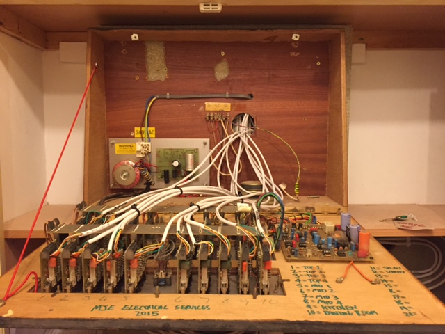
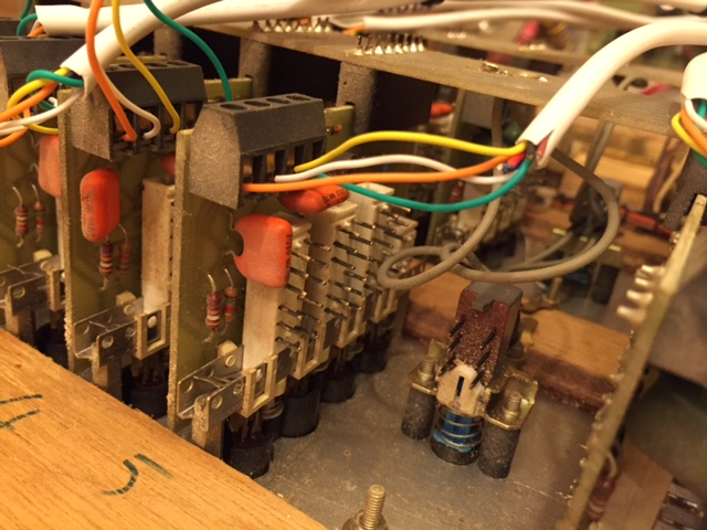
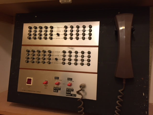
For interest, and context, here's a few photos of the central unit...

Central unit fascia Central unit internal Central unit room wiring close up

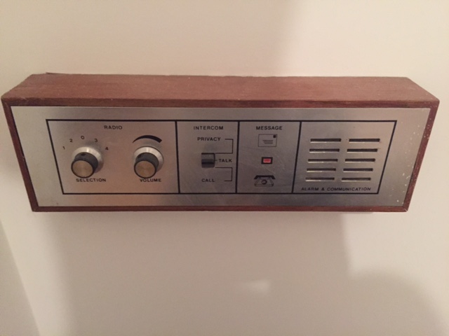
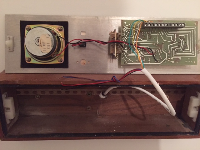
And the room units...

Room unit fascia Room unit internal

Now though the intercom works, the radio does not. I suspect there is no radio function in the central unit, and probably never was, though this might be an ignorant assumption on my part. I see nothing that looks like tuners (of which presumably there should be four (one for each channel on the room units)), and the chips all seem like either non audio, or stuff like op-amps and attenuators that one suspects are for the intercom audio, nothing especially obviously radio like specifically. As you can see from the photos, the circuit boards are pretty old technology.

Since radio reception in the area is truly dire even by roof aerial (and there is no roof aerial connection available near the central unit even), this might in any case be no great loss, so I was wondering if I could achieve a modern upgrade/addition to the system; an addendum to its history, in the form of internet streamed radio supplied from the central unit!

So my (first) sub question is actually, is it reasonable to expect the room units have amplifiers, and hence I should not be thinking of providing real speaker driving power from the central unit to the rooms or is this system more likely designed with all the driving power achieved in the central unit? I realise no one can know this unless they've come across a very similar system, but I imagine there is a more sensible design option that has likely been followed. Clearly any power for amplification must go over the Cat5 too, as there is no power delivered to the units separately.

If there are amplifiers in the room units, would the Raspberry PI audio out or other USB audio outputs need amplification? There seems to be enough power in such things to drive small headphone type speakers at least, so does that mean driving a bunch of amplifiers with quite a bit of cable in between is OK and can I just connect all of them in parallel or am I out of my mind?

If there not amplifiers in the room units, should I be thinking of one amplifier capable of driving all the units at once, or many separate drivers? And if I drive them from the central unit like this, should I add the impedance of the wires to that of the speakers when considering sizing?

Any extra comments/advice is of course welcome. I'm happy to do research and work at it a bit, but though I am slowly trying to get into electronics, I'm still at the stage of feeling like it's wallowing through treacle; I'm liable to make dumb mistakes on a project like this if I'm not careful.

I have 4 wires to work with, because the electrician used 4 of the 8 Cat5 cores. Not sure if this means I can get all 4 radio channels going or not, in my mind it seems possible, if one of the other wires is a ground, then there are 4 wires for 4 radio stations, but there are eight unused connections on the wall units (most of which seem to go to the radio channel knob) which worries me a bit, but if I could get one channel going only that would still be a great thing, because if nothing else my mum is a great radio fan and would love to go from room to room switching radio 4 on and off without carrying around a radio (which works very badly if it works at all anyway).

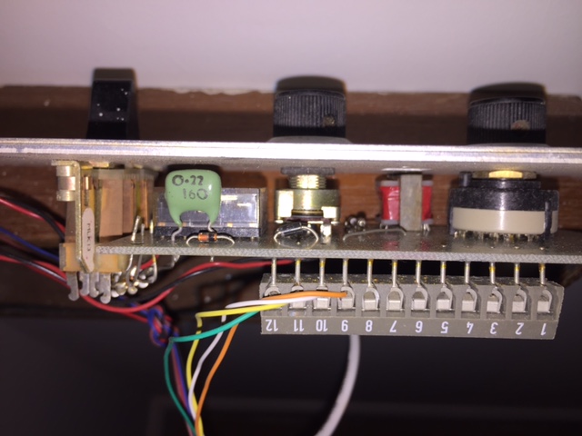
Edit (following answer post): not ideal, but I do also have this photo peering inside the wall unit! Not a lot to see, a capacitor, a few diodes probably, transformer. There's obviously not a huge amount, though there is something big and shiny I can't guess at.

Room unit, circuit board edge on

\$\endgroup\$
6
  • 1
    \$\begingroup\$ That's some beautiful vintage hardware, which makes me feel dirty for suggesting a digital approach -- use those pairs for Ethernet, and then cram a small RPi + custom board at each node to interface with existing switches, knobs, etc. Just another idea :) \$\endgroup\$ Commented Dec 28, 2015 at 18:16
  • \$\begingroup\$ @KrunalDesai I pondered the issue of desecration of the beautiful vintage hardware, and talked to my parents about it. Their view is things are better used and loved than becoming a monument/gravestone, and modern parts/replacements/additions just becomes part of its history, character and story. Within reason of course. In this case, it'll never have vintage radio capability I think, and any upgrade of this sort is removable, so I think it's fine. \$\endgroup\$
    – Michael
    Commented Dec 28, 2015 at 19:12
  • \$\begingroup\$ @KrunalDesai A raspberry PI per room unit is a good extra suggestion, though I don't know what the power arrangement is currently via the 4 already used lines... I guess as long as one can tap those to power the RPI it could be an option. I wonder if it would be possible to do it without modifying the room units (which I'm against). It may well be possible with a bit of cleverness. Bit expensive maybe though buying a Raspberry PI per room. I shall have to think about it. Very welcome comment though. \$\endgroup\$
    – Michael
    Commented Dec 28, 2015 at 19:25
  • \$\begingroup\$ I think with four wires you can do 10-100Mbit Ethernet + PoE (Power over Ethernet) -- 10Mbit is more than enough for audio, I'm sure. \$\endgroup\$ Commented Dec 28, 2015 at 19:27
  • \$\begingroup\$ @KrunalDesai Ahh right! I shall look into that, that would be better really, tapping power from the vintage central unit to power lots of RPIs sounds a bit risky without some very careful analysis that I could get wrong, so keeping them separate seems like a good idea. As you say 10Mb is tonnes of bandwidth, enough for 80 streams! \$\endgroup\$
    – Michael
    Commented Dec 28, 2015 at 19:31

2 Answers 2

2
\$\begingroup\$

There's some lovely 60s brushed-aluminium-and-wood casework there! And quite a decent job by whoever renovated it, and did you the favour of labelling the wiring on the inside of the case.

You might get a better reception on /r/electronics than here, due to the open ended nature of the question. Step 1 has to be to reverse-engineer the original system, either by finding its original service manuals on the internet or by drawing a circuit diagram from the single-sided PCB. It's quite clear from just looking at it that all those unused screw terminals connect to the four-position radio channel switch. It looks like there is no local tuner as you say, the switch selects an audio signal from the screw terminals. Whether it amplifies it locally is unclear: we could do with a photo of the other side of the PCB, which will involve taking the knobs off (grub screw visible at top) and undoing the nuts on the shafts. I suspect (given your comment about power) it doesn't amplify it locally, or the amplification is only for the microphone (which I can't locate visually).

\$\endgroup\$
6
  • \$\begingroup\$ Thanks for your comment about /r/electronics, I'll look it up and maybe if there isn't much interest here I can repost. Googled for data on it already but found nothing at all like it sadly - just too old and uncommon I guess. Googling the name on the fascia is also no good - too generic a name. I posted an extra photo, with the camera peering down the side of the room unit circuit board, not ideal but it's all I have now, when I'm at my parents place next I'll do as you say and take it to bits to get a proper look. \$\endgroup\$
    – Michael
    Commented Dec 28, 2015 at 17:16
  • \$\begingroup\$ I'm not sure there is a microphone on the room units BTW, we didn't manage to talk back to the central unit from the room, though broadcasting to the rooms from that phone thing works. It's possible we weren't doing something right of course, and the room unit clearly has a 'talk' position for that central switch. Surely one would expect it to be exposed on the fascia though if it were there, and there don't seem to be any holes apart from the speaker grill, and only two wires go there... \$\endgroup\$
    – Michael
    Commented Dec 28, 2015 at 17:19
  • \$\begingroup\$ It is possible they are using the speaker as the microphone also. If that is the case, there may be enough drive power created from the speaker to send poor quality audio back to the main unit... \$\endgroup\$
    – MadHatter
    Commented Dec 28, 2015 at 17:22
  • \$\begingroup\$ @MadHatter Right, I did wonder about that actually even as I write the above comment, but dismissed it as impractical / unusable. I knew this was kind of theoretically possible, but wasn't sure if a speaker, even in relatively ideal conditions, could really reproduce enough fidelity to be of any real use. \$\endgroup\$
    – Michael
    Commented Dec 28, 2015 at 17:27
  • \$\begingroup\$ So I have used modern plastic cone speakers of ~1in dia to act as a speaker / microphone and the quality was surprisingly good. Old cloth speakers may not be nearly as ideal, I'm not sure. \$\endgroup\$
    – MadHatter
    Commented Dec 28, 2015 at 17:29
0
\$\begingroup\$

I'm offering this as a general answer for all to edit as we figure out what's what. Please feel free to edit. Don't upvote or I get all the credit.

CENTRAL UNIT

BEDROOM UNIT

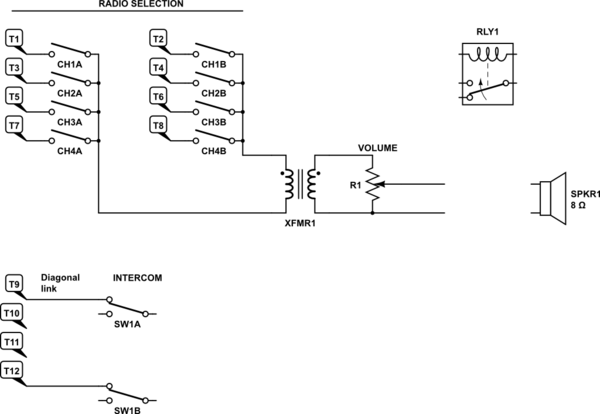
Radio Channel Select

  • The channel select switch is configured as 5-way double-pole selector switch with centre off: 1 - 2 - 0 - 3 - 4.
  • The wipers are connected to the small transformer which is probably a 110 V line speaker transformer. It appears then that the sound was distributed on 4 x 110 V line pairs, probably twisted to prevent cross-talk.

schematic

simulate this circuit – Schematic created using CircuitLab

That leaves us with four terminals. Functions to be figured out:

  • Message light. Is this latched by the relay?
  • Panel switch: privacy - talk - call.
  • Using the speaker as a microphone.
\$\endgroup\$
4
  • \$\begingroup\$ Unfortunately, I rather suspect pjc50 was right to say the first step is some reverse engineering. I wish I'd taken one of those units off the wall and brought it home with me now so I could analyse it in depth at my leisure, but as it stands I'm not very well equipped to fill in the blanks until I can get back there in a month or so (not exactl around the corner, 5+ hours travel) armed with diagnostic equipment. Everyone's comments have focused my mind on the importance of properly understanding the room units now in a way it wasn't before though. \$\endgroup\$
    – Michael
    Commented Dec 28, 2015 at 23:42
  • \$\begingroup\$ The message light does work BTW, it lights up when the appropriate buttons are pressed on the central unit. I may not have thoroughly enough investigated the intercom w.r.t. microphone, I didn't really think about it at the time even to the point of not finding the mic, let alone considering the use of speaker as mic. So again, it'll have to be something I follow up on when I'm there, and I should try another unit, just in case that one (nearest the central unit) has a fault of any sort. \$\endgroup\$
    – Michael
    Commented Dec 28, 2015 at 23:45
  • \$\begingroup\$ It sounds like if you simply turn the unit volume knob up and then apply gradually increasing "line" (1V) level audio (NOT a power amp at this stage) to the correct terminals that are switched in for a channel, you might get something out of the speakers. If the transformer is in the circuit and not 1:1, it will be a en.wikipedia.org/wiki/Constant-voltage_speaker_system and you need a matching transformer on the other end. I disagree with the "Pi in every unit" suggestion as you can get 3 channels easily enough from the 4 wires and a single driving unit of some sort. \$\endgroup\$
    – pjc50
    Commented Dec 29, 2015 at 10:27
  • \$\begingroup\$ @pjc50 A "Pi in every unit" would certainly provide ultimate in capability... and make some things very easy... but it would represent a solution further removed from the original vintage solution, and it would be very expensive. By the time one had bought 10+ RPIs, amps, mode A PoE adapters, a large PoE switch, and other bits and bobs, I think the bill would be over £500, maybe a lot more. And it'd add a few Watt hours to the monthly electric bill :) As you say 3 channels should be possible, maybe 4 if there is a useful ground already. Thanks for that link, very good pointer! \$\endgroup\$
    – Michael
    Commented Dec 29, 2015 at 12:32

Your Answer

By clicking “Post Your Answer”, you agree to our terms of service and acknowledge you have read our privacy policy.

Not the answer you're looking for? Browse other questions tagged or ask your own question.