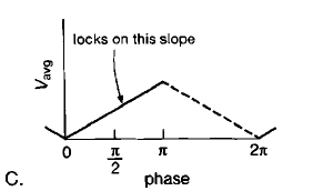
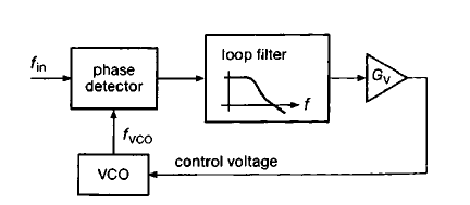
For Phase locked loop (PLL), we can have two types of Phase Detectors (PD): Type-1 and Type-2. The Type-1 PD has an analogue multiplier (which is simply XOR for digital inputs) whose low pass filtered output is a signal which varies at a frequency equal to the difference between the input and Voltage Controlled Oscillator (VCO) frequency. The voltage v/s phase plot of such a PD looks like this:

For this PD, the rising slope provides a negative feedback for the PLL loop but the falling slope provides a positive feedback. Why is that? And, as shown in the figure the PLL locks on the rising slope, so what parameters of PLL decide where on this slope the PLL would lock? Does it depend on the input frequency as well?
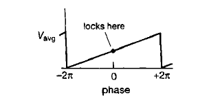
The Type-2 PD has a digital circuitry of flip-flops whose output depends only on the relative time shift of the input edges and has the average voltage v/s phase characteristics as shown below:
Why would a PLL with this type of PD not lock if the phase difference input to the PD is greater than \$2\pi\$?


