3
\$\begingroup\$

I have just disassembled a RC car. Attached to the stepper motor that controls the steering of the car was a small circuit board with a cog wheel attached to it. I am trying to figure out what this circuit does. My idea is that it is responsible of keeping track of the wheels position but I am not certain. Here is a picture of it:enter image description here
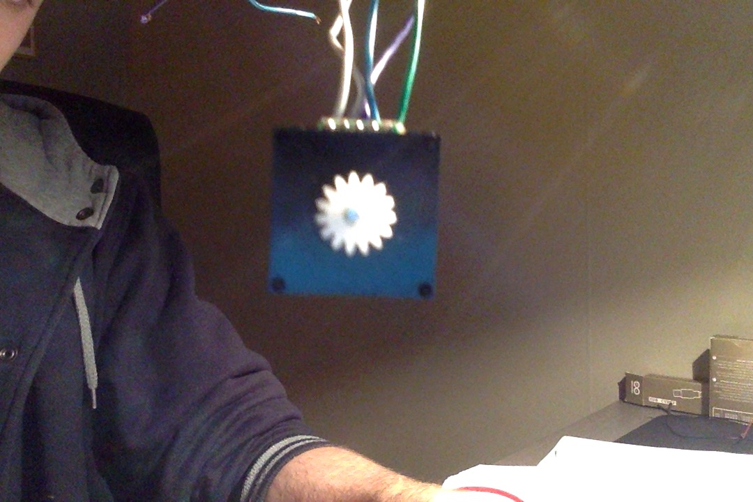
As you can see there are 5 wires coming out of it and I know that the green one is GND. Does anyone have an idea of what its function might be?

EDIT:

I connected the green wire(GND) along with all the other wires (one at a time) and measured the resistance for different positions of the cog. This is what I came up with: enter image description here

The grey areas are the zones where R < 1 Ω, i.e current could flow. The areas marked with OL are areas with a huge resistance, i.e no current could flow. I have tried to grasp these results but failed. To me it does not seem logical, there is no symmetry...

\$\endgroup\$

4 Answers 4

1
\$\begingroup\$

Based on your update and resistance measurements it is a 4-bit rotary encoder with wiping contacts.

enter image description here

Binary and gray encoded 3-bit rotary encoders. Image from Wikipedia.

The image shows two different 3-bit rotary encoder patterns. (Yours is 4-bit as it has four contacts.) The left pattern is a regular binary pattern. The contacts are represented by the yellow circles. White is no-contact. Black is contact.

You can see that as we rotate the encoder disc anti-clockwise we will get a binary pattern:

0 0 0
0 0 1
0 1 0
0 1 1
1 0 0
1 0 1
1 1 0
1 1 1

This all would be fine until you line up on the boundary where two bits change simultaneously - e.g. 001 to 010. Now if the contacts aren't exactly aligned (and they never will be) what you read may go 001, 000, 010 or 001, 011, 010 as the contacts change over. This would present spurious position readings to the software trying to keep track of position. Note that going from 111 to 000 is the worst!

The Gray code solves this by only allowing one bit to change at a time. In this case our sequence would be:

0 0 0 
0 0 1
0 1 1
0 1 0
1 1 0
1 1 1
1 0 1
1 0 0

Here we can see that the code changes by one bit at each transition. Note that the software now needs to be able to decode the Gray code - usually by lookup table.

Test your encoder as shown below and record your results.

schematic

simulate this circuit – Schematic created using CircuitLab

Put the results into your original question. It may help someone else.


For an Arduino application you would connect the common to GND and connect the switches to the Arduino inputs. Set the Arduino pinMode() to INPUT_PULLUP which will connect a 20 - 50k resistor internally to each pin so configured.

\$\endgroup\$
2
  • \$\begingroup\$ New answer. If this is right you may move the 'correct answer' flag to this one. I'll leave the other answer up there as it may help someone else. \$\endgroup\$
    – Transistor
    Commented Jan 10, 2016 at 14:20
  • \$\begingroup\$ I will post my results soon \$\endgroup\$
    – samtob
    Commented Jan 13, 2016 at 12:57
1
\$\begingroup\$

Since you said this was attached to a stepper motor, it's most likely a rotary position encoder. The stepper motor can move the steering incrementally in small steps either direction, but the system still needs to know where it is, like how far from center. That's probably what your geared thingy does.

If you hadn't said this was connected to a stepper motor, I would have guessed this is the stepper motor.

\$\endgroup\$
1
\$\begingroup\$

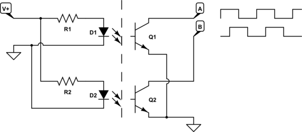
Possibly a quatdrature encoder similar to one axis of a 'ball-type' mouse though this could be achieved with only four wires.

schematic

simulate this circuit – Schematic created using CircuitLab

A slotted disk runs between two slot sensors. The two are set up 90° out of phase.

  • If 'A' is high when 'B' goes high then count up.
  • If 'A' is low when 'B' goes high then count down.

schematic

simulate this circuit

For steering it might be useful to know where straight ahead is. In this case a 'Z' or zero pulse may be generated at a certain position. This would imply that the encoder would not, in normal operation turn a full circle either size of centre - otherwise multiple positions could report 'home'.

In operation, the car would initialise by running the steering left and right until it finds the zero position and then counting A and B pulses from there on.

The two-phase + Z encoder also has the advantage, as far as this problem goes, that it requires five wires!


Checking

If this answer is correct you should be able to detect the LEDs using a multimeter - provided the diode test function uses > 2 V. The LEDs will probably be infra-red and will have a forward voltage drop of about 1.2 - 1.4 V.

  • If you have a regular red LED to hand then test your meter. Switch to diode range, connect black to cathode (small flat on side of standard LED) and red to anode (usually the long lead). The meter should read about 1.8 V. If that works ...
  • Connect meter black to encoder common and test each of the other four pins for conduction. If our hunch is right then you should find one of the pins reads. If so ...
  • Hook up a temporary supply to the LED side. Here you're going to have to use some deduction and figure out what the car would have supplied to the LEDs. It will either by the logic PSU (5 V?) or straight from the battery. 5 V shouldn't do any damage. If you connect the meter in series with your temporary power you should see about 10 - 40 mA on the meter.
  • With the LEDs powered up and the black wire still on common probe the other wires while slowly turning the cog wheel. If there's a photo-transistor we should see the meter read hi and low as the slots pass the opto-coupler.
\$\endgroup\$
3
  • \$\begingroup\$ Thank you! Though, how do I know which cable goes where? \$\endgroup\$
    – samtob
    Commented Jan 10, 2016 at 10:32
  • \$\begingroup\$ For example if I where to connect it with my Arduino where would the cables go? \$\endgroup\$
    – samtob
    Commented Jan 10, 2016 at 11:06
  • \$\begingroup\$ @samtob: Thanks for accepting my answer but it is completely wrong! New answer coming up. \$\endgroup\$
    – Transistor
    Commented Jan 10, 2016 at 13:53
0
\$\begingroup\$

it's the feedback pot and circuit that decodes the PWM commands and drives the motor

\$\endgroup\$

Your Answer

By clicking “Post Your Answer”, you agree to our terms of service and acknowledge you have read our privacy policy.

Not the answer you're looking for? Browse other questions tagged or ask your own question.