4
\$\begingroup\$

I am in the process of solving a DE for a circuit.

So: the circuit starts with a voltage source of 5 VDC and is allowed to reach steady state. At time t = 0, the source is switched out for a 10 VDC source. schematic
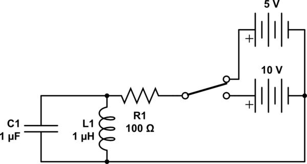
I am in the process of finding the initial conditions: $$i_L(0^+)\ \ \mathrm{and}\ \ i_L'(0^+)$$

Clearly, $$v_C(0^-) = 0\ \mathrm{V}\ \ \mathrm{and}\ \ i_L(0^-) = \frac{5\ \mathrm{V}}{100 \ \Omega}$$

So $$i_L(0^+) = 50\ \mathrm{mA}$$

Now, to find iL', I said $$v_L = Li_L'\ \ \mathrm{and}\ \ v_L = v_C$$

So $$i_L'(0^+)=\frac{v_C(0^-)}{L} = 0\ \frac{\mathrm{A}}{\mathrm{s}}$$

But, if you simulate this circuit and flip the switch, the slope of the current through the inductor is clearly not zero.

Am I doing something wrong, or is there something subtle happening?

Thanks

\$\endgroup\$
2
  • \$\begingroup\$ The current in an inductor can't change instantly, but the derivative can. \$\endgroup\$
    – Greg d'Eon
    Commented Jan 19, 2016 at 1:00
  • \$\begingroup\$ Yes, I am aware of that. The problem I'm having is that the (apparently) correct math shows an initial derivative of zero, even though the simulator disagrees. \$\endgroup\$
    – Mahkoe
    Commented Jan 19, 2016 at 1:03

2 Answers 2

4
\$\begingroup\$

[ last line should be i'L(0+) ] Your calculations are correct. At t=0+, there is 50 mA in the inductor, but 0 V across it (and the capacitor). So i'(L) =0. Now, the voltage across the capacitor will increase (because supply increased from 5 to 10 V; the 'extra' 50 mA will flow in the capacitor. The cap voltage will rise, and then the inductor current will increase.

In a small region around 0+, the cap V will increase linearly, and inductor current quadratically with time, however overall the result will be (exponentially decaying) sinusoids.

Clearly at the extreme of a sinusoid, the derivative is 0, yet since the 2nd derivative isn't 0, the derivative will change, and so will the value.

\$\endgroup\$
3
\$\begingroup\$

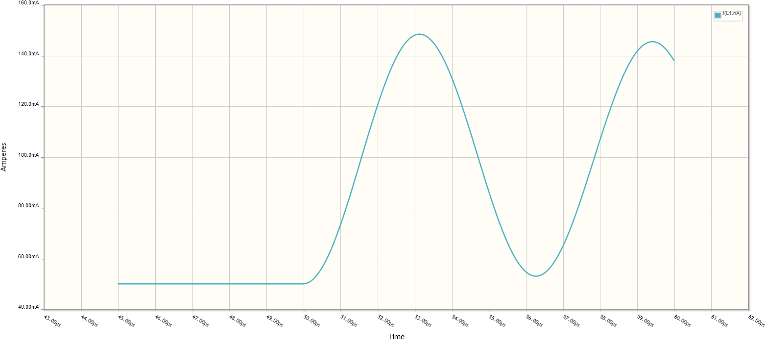
Are you sure you did the simulation correctly? I found that at the moment the voltage source changes, the slope of the inductor current is zero:

CircuitLab sim

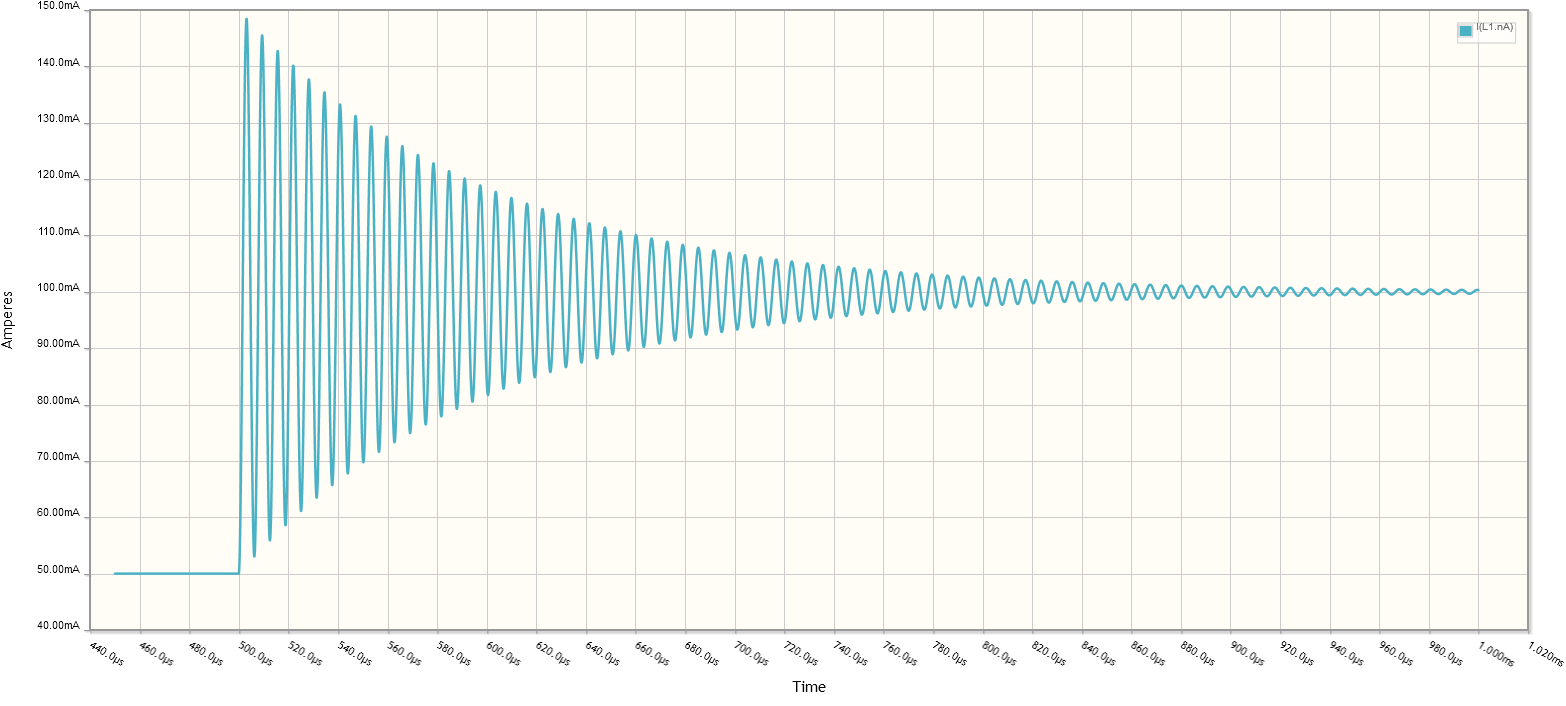
You can see that the oscillation starts in the trough of a sine wave, where the derivative is zero. Here's a longer view showing the exponential decay of the oscillation:

Another CircuitLab sim

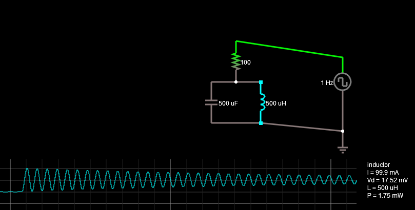
UPDATE: I get the same result with Falstad:

Falstad simulation capture

It's harder to see because you can't zoom in easily. I had to increase the inductance and capacitance to get this much. But you can see that the ringing starts in the trough of a sine wave, where (as jp314 points out) the derivative is zero. If you crank up the plot speed and move the simulation speed around you can get a better view:

A zoomed in Falstad sim

Falstad is great for visualization, but getting precise results is awkward. For transient simulations, I recommend using CircuitLab, which you can use for free in an EE.SE answer box.

\$\endgroup\$
2
  • \$\begingroup\$ Huh. I guess my simulation program doesn't have reliable results then. (I use the falstad circuit simulator: falstad.com/circuit/circuitjs.html) \$\endgroup\$
    – Mahkoe
    Commented Jan 20, 2016 at 0:17
  • \$\begingroup\$ I updated my answer with Falstad results. \$\endgroup\$
    – Adam Haun
    Commented Jan 20, 2016 at 3:09

Your Answer

By clicking “Post Your Answer”, you agree to our terms of service and acknowledge you have read our privacy policy.

Not the answer you're looking for? Browse other questions tagged or ask your own question.