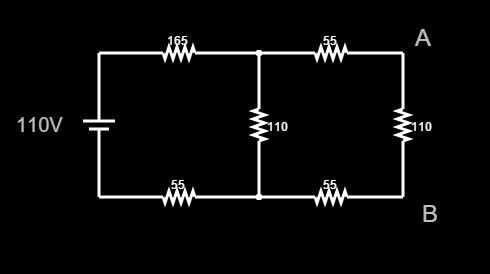
As you already know, computing a Thevenin Equivalent involves 2 parts:
- Computing \$Z_{TH}\$
- Computing \$V_{TH}\$
Obtaining \$Z_{TH}\$
As you have already computed it I am going to discuss briefly how I would get it to see if we agree.
After shorting out the voltage source we find that:
$$Z_{TH} = (165 + 55)//110 + 55 + 55 = \frac{(165 + 55)·110}{165 + 55 + 110} + 55 + 55 [Ω]$$
Where (//) denotes the parallel of those resistors and (+) the series equivalent. Note how the // operation takes precedence. Carrying it out shows \$Z_{TH} = 183,83 Ω\$
Obtaining \$V_{TH}\$
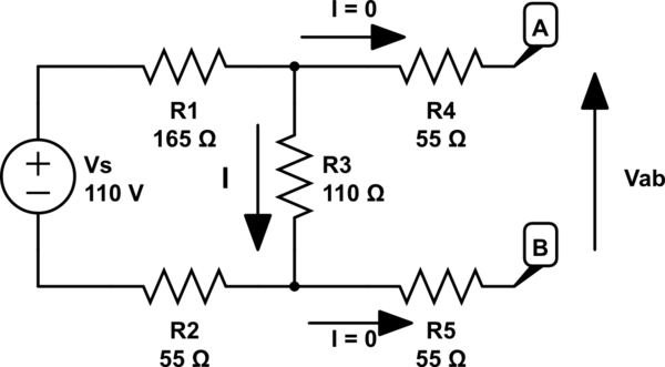
As you pointed out, having an open circuit between terminals A and B "removes" all the resistors in the right mesh from the circuit (namely both 55 and the right-most 110 ohm resistors). We also see how \$V_{AB} = V_{TH}\$ is indeed the same as \$V_{R=110}\$. The only thing we have to do is obtaining that \$V_{R=110}\$. To do so we will solve the left-most mesh. Obtaining the current follows Ohm's law and it is given by:
$$I =\frac{V_{Source}}{R_{165} + R_{110} + R_{55}} = \frac{110V}{165Ω + 110Ω + 55Ω} = 0,33A = 333,33mA$$
Then: $$V_A = V_B + I·R_{110} \to V_A - V_B = V_{TH} = I·R_{110} = 0,33A·110Ω = 36,67V$$
If you want to see the "equation" for the voltage divider you can just substitute I in the second equation for the expression we obtained in the first one and you would get:
$$V_{TH} = \frac{V_{Source}}{R_{165} + R_{110} + R_{55}}·R_{110}$$
Finally, here is the circuit with the current I used:

simulate this circuit – Schematic created using CircuitLab


