1
\$\begingroup\$

I am trying to build a circuit with 2 inputs and 1 output using Mosfets.

I will try to explain what I want..

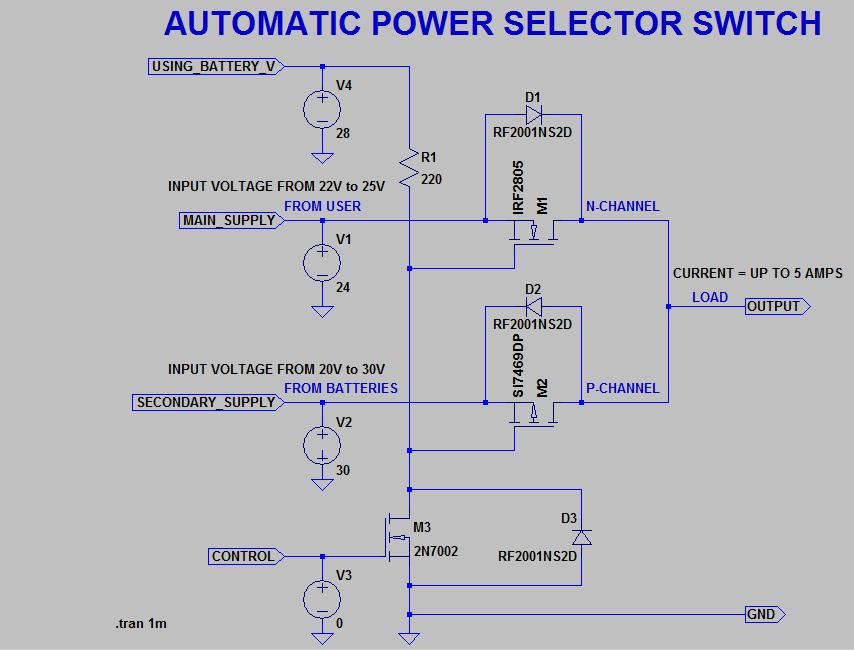
The circuit should accepts 2 input DC voltages , the first input voltage called "MAIN_SUPPLY" which will be the "ALWAYS ON" input that may vary between 22VDC to 25VDC. If the main supply goes OFF then my output LOAD should switch to the secondary input which will be treated as batteries (AS BACKUP) .. Battery Voltage may change from 20V to 30V (Due to the charging).

The circuit image is below , it should work for input voltage below 20V due to the absolute maximum ratings for VGS for each mosfets .. I am unable to make this circuit work with 24V system . Is there a solution for me to use the same circuit 24V system or is there another circuit that would help me .

I chose to use mosfets , because they can switch fast (nano seconds). I have 3 routers with a total power consumption of about 30 to 40 Watts.

The below ciruit shows a complementary design using N-channel and p-channel .I don't have a problem with the P-CHANNEL mosfet . My problem is IRF2805 as its Max VGS +20VDC and i require +30V. Because I am applying 24VDC to the source pin of IRF2805 that means Gate pin must have higher voltage than its source .

When the 2N7002 or similar control MOSFET ties the gates together and pulls them to ground, the p-channel MOSFET is on. Pulling the gates above the supply rail by turning the 2N7002 off results in turning the n-channel MOSFET on. Pulling the gate of the p-channel MOSFET above the source potential has no effect; the MOSFET remains off with low leakage. The resultant switch is a break-before-make configuration, which is necessary to ensure that the secondary, or always-on, supply never has to power the whole circuit.

the label NET [USING_BATTERY_V] is to charge the gates of nmosfet an pmosfet. N-channel has no effect on that . [USING_BATTERY_V] has to be always ON 28VDC. p-channel is affected and it stops 30V to pass thus allowing MAIN_SUPPLY to pass . When we charge the gate of 2N7002 then it turns off all gates and the load switch to secondary_supply. I have rb260gsp as a router and it accepts voltage from 12 to 30VDC so I don't get hurt if the 2 supplies have different voltages.

I don't want to work with surface mount parts.

I can buy any part online .

Is there any mosfet p-channel and n-channel that accepts VGS up to 30VDC.?

I really appreciate your help.

enter image description here

\$\endgroup\$
8
  • \$\begingroup\$ What are your design constraints? Cost, assembly capability, parts availability? \$\endgroup\$ Commented Jan 25, 2016 at 0:02
  • \$\begingroup\$ The above ciruit shows a complementary design using N-channel and p-channel .I dont have a prblem with the P-CHANNEL mofet . My problem is IRF2805 as its Max VGS +20VDC and i require +30V. Because I am applying 24VDC to the source pin of IRF2805 that means Gate pin must have higher voltage than its source . I can buy any part online . Is there any mosfet p-channel and n-channel that accepts VGS up to 30VDC.? \$\endgroup\$
    – Ghassan
    Commented Jan 25, 2016 at 0:19
  • 2
    \$\begingroup\$ Your explanation seem incomplete. What does USING_BATTRY_V do? What does CONTROL do? Your initial description sounds like: a load must always be powered, the MAIN input is 22-25V, and should be always be used unless it fails. When MAIN fails, SECONDARY_SUPPLY should take over, quickly enough that the load always sees a minimum of 22V. There doesn't seem to be any need for USING_BATTERY. CONTROL appears to be On/Off, but is either not explained, or its requirements need to be explained. \$\endgroup\$
    – gbulmer
    Commented Jan 25, 2016 at 0:21
  • 1
    \$\begingroup\$ Please update your question with extra information about the circuits requirements. That makes it easier for everyone to be on the same page, without needing to read all the comments. \$\endgroup\$
    – gbulmer
    Commented Jan 25, 2016 at 0:39
  • 1
    \$\begingroup\$ Please update your question with extra information about the circuits requirements. That makes it easier for everyone to be on the same page, without needing to read all the comments. \$\endgroup\$
    – gbulmer
    Commented Jan 25, 2016 at 1:22

2 Answers 2

3
\$\begingroup\$

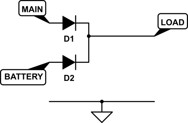
IFF the SECONDARY_SUPPLY battery voltage were less than MAIN, the entire circuit seems to be two diodes.

schematic

simulate this circuit – Schematic created using CircuitLab

So, the extra complexity comes from the battery voltage being higher than MAIN.

So one solution is to lower the battery voltage, or raise the mains voltage.

Alternatively, only control the battery source, and use a diode to protect MAIN.

A comparator could compare the two voltages (MAIN and BATTERY), and when main drops too low, switch on a P-MOSFET, connecting BATTERY to LOAD.

Remove the need for nano-second switch time by using a large capacitor. 100,000µF+ should supply current (5A) long enough to raise the switch time to milliseconds.

\$\endgroup\$
2
  • \$\begingroup\$ do you know of any comprator that is availabe in LTSPICE that would work with the circuit i draw above. I appreciate if you attach your circuit with comparator added \$\endgroup\$
    – Ghassan
    Commented Jan 25, 2016 at 1:23
  • \$\begingroup\$ @user3450944 - sorry, I'm not an LTSpice user. \$\endgroup\$
    – gbulmer
    Commented Jan 25, 2016 at 2:49
0
\$\begingroup\$

Recently, I need to design similar circuit with different specification. I would like to use suggestions already posted.

Alternatively, only control the battery source, and use a diode to protect MAIN.

As suggested by gbulmer, this is a good approach to make automatic voltage source selection. But right component selection is primary criterion to come up with good design which follows all voltage and current specifications.

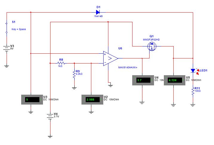
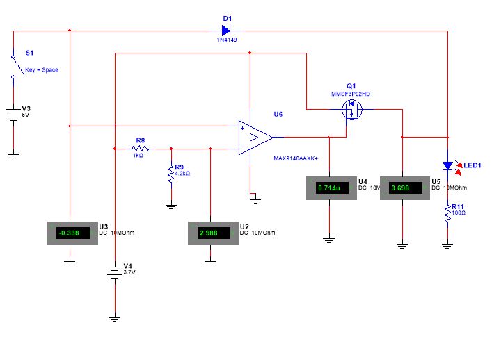
A comparator could compare the two voltages (MAIN and BATTERY), and when main drops too low, switch on a P-MOSFET, connecting BATTERY to LOAD.

Exactly, a comparator would be better option for coming up with this analog logical circuit configuration. My selected comparator is for low voltage application, you need to select high voltage comparator.

Switch closed and LED is getting power from 5V main supply.

Switch open and LED is getting power from 3.7V secondary backup supply.

Remove the need for nano-second switch time by using a large capacitor. 100,000µF+ should supply current (5A) long enough to raise the switch time to milliseconds.

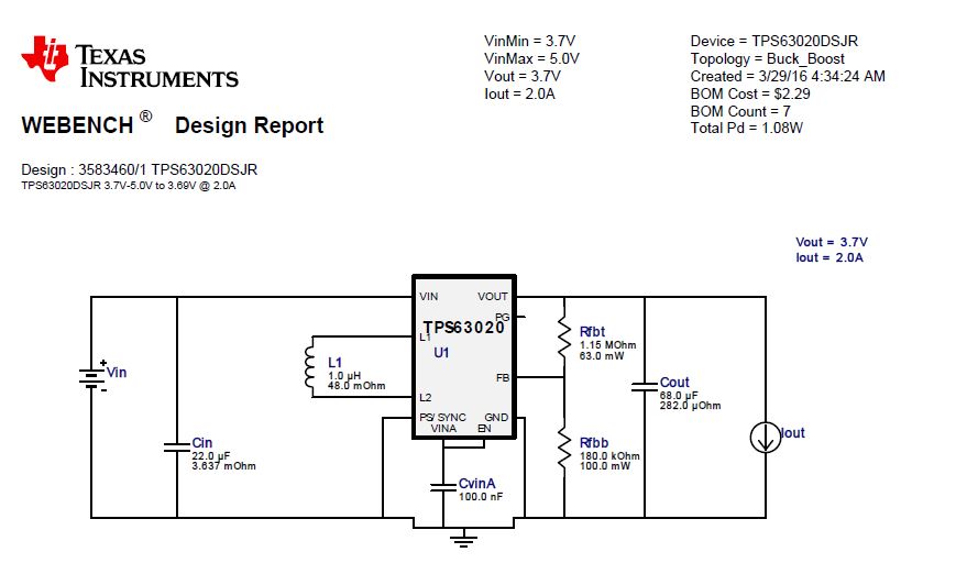
My load circuit needs at least 2A current along with 3.7v regulated power supply. Since main supply is 5V, I have used a buck converter and fully verified TI webench design provides the solution. I hope this approach will provide you desired solution.

3.7V/2A regulated buck-boost converter

\$\endgroup\$

Your Answer

By clicking “Post Your Answer”, you agree to our terms of service and acknowledge you have read our privacy policy.

Not the answer you're looking for? Browse other questions tagged or ask your own question.