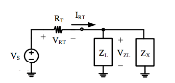
So I needed to find a value for a capacitor (Zx, where the resistive component is zero) to perform power factor correction (PF = 1) on the following circuit:
w = 1250
ZL = (98.1+157.5)+j(1250)(0.15) Rt = 1k
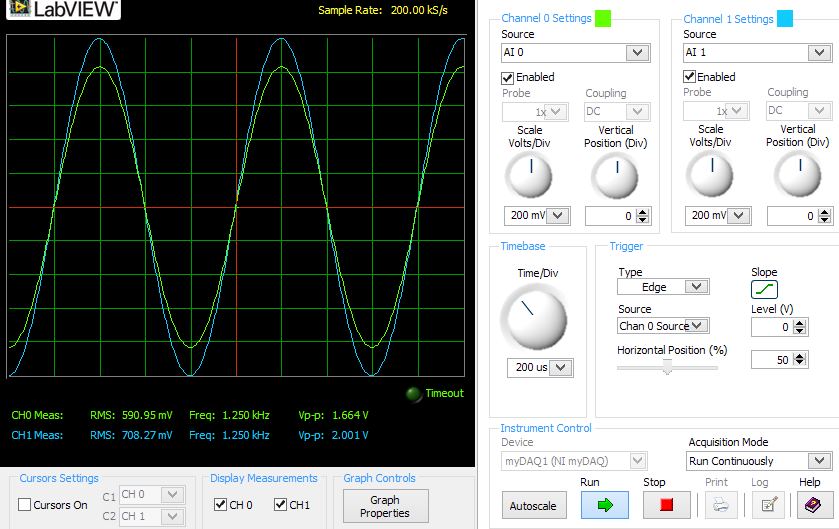
I calculated that I need a capacitor with value C = 1.032E-7F, so I used a 0.1uF cap and measured voltage waveforms of the source and load with the NI MyDaq (garbage, but we have to use it for our lab class.) I realized that I need to be looking at the current waveform though. I obtained the following waveform:
This shows the voltage of the capacitor/load node is in phase with the source. However, I have no way of measuring current. I know that i = C(dv/dt) for the capacitor. So the current waveform would be 90 degrees out of phase with both voltage waveforms. Similarly, the inductor equation for current (Zl has an inductor of L = 0.15 H,) has an integral so it introduces a phase shift.
My question is as follows:
Is looking at the voltage waveform for the inductor and capacitor and deducing the fact that each respective current's phase offset will cancel with the other enough to say that we actually have achieved a unity power factor?


