2
\$\begingroup\$

I want to replace some timers with a PIC16F887 micro-controller. The problem is that the input voltages to the I/Os is going to be 24V which is too much. For the output part I was thinking about using a relay module. I'm stuck on the input part. How can I use the 24V as a input to the micro-controller?

The application is simple. When a input pin goes high the output will be enabled after a certain period of time (When 24V is received from the input the output will send 24V in other words). The time will be adjustable trough some push buttons. The times will be displayed on a LCD.

This question is tied to a different question I asked from the forum before. A user recommended a similar cheap solution which is already made but I want to build one just for a personnel project.

\$\endgroup\$
2
  • 2
    \$\begingroup\$ Use optoisolators for the inputs. Just like the board you linked uses optos to isolate the relays better. Do not go cheap or you will likely be sorry. \$\endgroup\$ Commented Jan 26, 2016 at 7:22
  • 4
    \$\begingroup\$ For a one-off home project this approach would be fine. Industrial control systems generally have long lifespan - 20 years would not be unusual. The advantages of manufacturer support, noise hardened hardware, proper cases and terminals, etc., far outweigh the money saved by a DIY solution. There are now many micro-PLCs with LCDs, 8 inputs, 4 outputs (typ. minimum), analog in, PWM out, etc., at around $100. \$\endgroup\$
    – Transistor
    Commented Jan 26, 2016 at 8:15

3 Answers 3

4
\$\begingroup\$

I don't know why you're using such a ancient PIC in a new project, but there is no reason it shouldn't work.

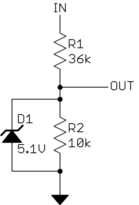
Scaling 24 V signals down to 5 V is as easy as a resistor divider. Something like this should work:

The resistors attenuate 24 V to about 5 V. The zener guarantees the voltage into the PIC is within what it can handle because stuff happens. The zener will also clip negative spikes, but to one diode drop, which is right about where the PIC starts misbehaving.

If you are really worried about negative spikes, then you can put a Shottky diode across the zener just to clip negative voltages. Or you can break up R2 into two resistors that attenuate a bit after the zener, and use a bit higher voltage zener to compensate.

There are lots more things you can do. It depends on how much you want to protect against. More protection will add complexity and cost, but robustness to ever less likely abuse. Only you can decide what the right tradeoff is.

\$\endgroup\$
2
  • \$\begingroup\$ So the 24V will be connected to zener diode and then to the input pin? I wanted to use this PIC because this is my first go at PICs. By the looks online this has a lot of examples available which is useful. \$\endgroup\$
    – Ian Moone
    Commented Jan 26, 2016 at 12:14
  • \$\begingroup\$ @Ian: No, the 24 V input is connected to IN, and the PIC input to the output of this attenuator, named OUT in the schematic above. \$\endgroup\$ Commented Jan 26, 2016 at 12:16
2
\$\begingroup\$

if you want to make something like a PLC out of PIC , i would advise you to look at similar designs done for arduino and nucleo.

Example 1: Ruggduino http://www.rugged-circuits.com/ruggeduino/
This board has all input pins protected against over voltage up to 24v and current limited using series PTC resistors. And multiple other features , it also open source so you can access the schematic and use it.

Example 2: X-NUCLEO-PLC01A1
This solution focus on using ICs especially for isolated interface for controllers , something like CLT01-38S4 and VNI8200XP. take a look at this shield for industrial stm32nucleo board : http://www.st.com/web/catalog/tools/FM116/CL1620/SC1971/PF261969

\$\endgroup\$
1
\$\begingroup\$

You can step down the input voltage of 24V to 5V/3.3V using a resistive divider and unity gain buffer. If the microcontroller is not able to drive the relay, then you may also need a transistor to increase the output current capability to drive it.

\$\endgroup\$

Your Answer

By clicking “Post Your Answer”, you agree to our terms of service and acknowledge you have read our privacy policy.

Not the answer you're looking for? Browse other questions tagged or ask your own question.