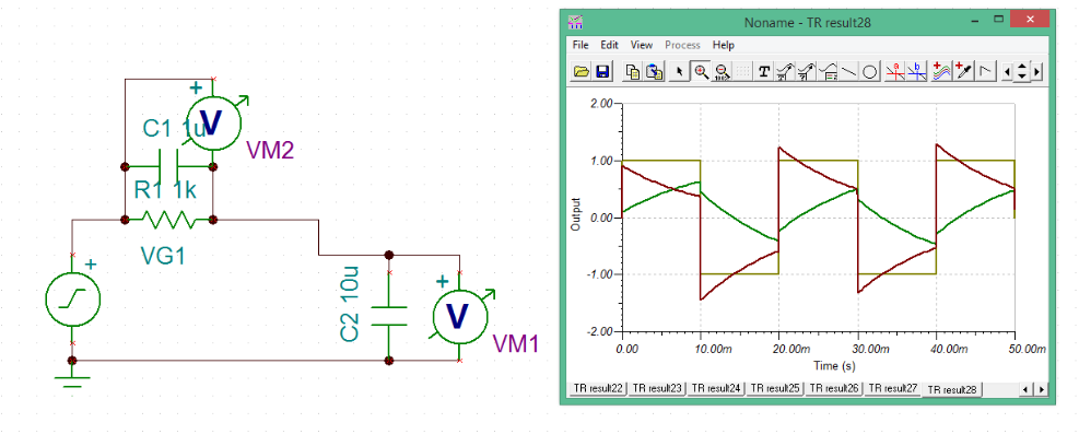
I simulated this circuit in TINA-TI. However I could not understand the output waveform for the negative half of the cycle.
Waveform: Green- Voltage across C2 (10 u cap) Brown- Voltage across C1 (1 u cap) Yello- the input square wave
For the first half at t=0, both the capacitors will charge instantaneously. Of course the capacitor with higher capacitance will charge to a lower voltage as compared to the smaller capacitor.
For t>0, C1 starts to discharge through the resistor R1 which means C2 must start charging so as to maintain an over all voltage of 1V at the input terminal.
However, in the negative half of the cycle the voltage for C2 remains positive and for C1 it drops to less than -1 volts. Why is the voltage of C2 not negative (similar to C1)? Why isn't voltage across C1 more than -1 volt and across C2 <0 such that VC1 + VC2 = -1 volt?

