0
\$\begingroup\$

Im trying to build a circuit to send information using IR led, using pulse signals my leds (TSAL6400) operates at 1.35V, and their maximum pulse current is rated 200mA

After struggling a bit with BJT transistors, and realizing that since I'll send the data using RPI (Gpio is 3.3V, 16mA), I switched to NMOS transistors. I found a local dealer with RFP30N06LE

Vgs(th)= 1-2V (min,max)
Rds(on)=0.047Ohm

My circuit (due to other limitations, and the fact I need to decide on which branch of leds to send the command on, each branch is a different room in my home) enter image description here
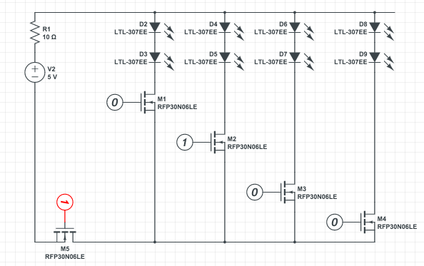
As I demonstrated in this sketch, each of the branches represents a room, and I want to each time send a command to a specified room. So, for instance, to send to the second branch from the left, I will turn the M2 on ("1" = 3.3V of my gpio at 16mA max), and will send the pulses by turning on and off M5 In order to reach 200mA I need a total voltage drop of 2.3V over my resistors and transistors. If R1=11.5Ohm, for M1-M4: Vds=0V, Vgs=3.3V Since Vds=0V will keep the transistor closed (no current flow), I assume I need to raise the voltage just a bit, but not sure how to make it appropriate for case with two transistors, one after the other. If I will use Rtot=8.5Ohm + 1.5Ohm + 1.5Ohm, and placing R1 where it is already, R2=1.5Ohm before M5 and another one after. Is that the correct way? This way: Vgs(M2)=3V Vds(M2)=0.3V Vgs(M5)=3V Vds(M5)=0.3V

Is that correct?

\$\endgroup\$

1 Answer 1

1
\$\begingroup\$

You do not need the extra resistors around M5, the circuit will work just as it is, but with R1 11.5 ohms.

Vgs(th) for those MOSFET's is between 1V and 2V, so you just use 2V which is the worst case in this circuit. The RPI outputs 3.3V so it can easily turn on M5. When M5 turns on its drain will be almost 0V, which means the source of M1 to M4 will also be 0V. The RPI can easily turn on M1 to M4 because the 3.3V output from the GPIO exceeds the Vgs(th). When M5 is turned off then it doesn't matter what happens with M1 to M4 because no current can flow in any case.

In addition I suggest that you do not need M5 for the circuit to work. You can send the IR data to one MOSFET M1 to M4, while keeping the other MOSFET's turned off.

Answers to your questions

How do I calculate the resistors required for the gates, in order to lower the voltage to 2V?

You don't need to lower the gate voltage to 2V. Unlike a BJT where you have to control Vbe, a MOSFET works with any gate voltage up to its maximum Vgs (this is for a digital circuit which is on or off). Just apply 3.3V from the GPIO. A MOSFET takes almost no gate current - it is specified as Gate-Source leakage current with a maximum of 10uA but is typically much less.

You don't actually need a gate resistor, since you don't need to drop any voltage. However, it is still a good idea to add one, especially to larger MOSFET's. The gate of a MOSFET looks like a small value capacitor which has to be charged up to turn the MOSFET on, which can result in a large current flow from the GPIO pin until the cap has charged. When I am driving it from a processor I prefer to limit this current to be within the current rating of the GPIO pin. In this circuit I would limit it to 10mA with a 330 Ohm resistor.

Also, Why is M5's drain almost and not exactly 0V?

When it is turned on the MOSFET has a small resistance between drain and source (rDS(ON) ID) which will drop a very small voltage when current flows through it. Hence, its drain is nearly 0V. In this circuit you can ignore it and assume it is 0V.

\$\endgroup\$
1
  • \$\begingroup\$ Thanks for clarification, however some more is still needed. How do I calculate the resistors required for the gates, in order to lower the voltage to 2V? Do I just assume max current (16mA) will flow there? Can I just take a multimeter, connect mosfet to 5V and GND and see the current flows to the gate? Also, Why is M5's drain almost and not exactly 0V? Linear equations for nmosfets tells Vds>0, and for my case all the voltage drops on the resistor and leds. Is it enough to just apply 2V on each gate, without making it having Vd>0 for every mosfet? \$\endgroup\$
    – e-r-a-n
    Commented Feb 8, 2016 at 5:53

Your Answer

By clicking “Post Your Answer”, you agree to our terms of service and acknowledge you have read our privacy policy.

Not the answer you're looking for? Browse other questions tagged or ask your own question.