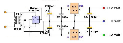
1. No. there is only one diode at a time doing the positive side rectification and one diode at at a time doing the negative side rectification, so at a maximum of 1 volt each, that's a 1 volt drop for the positive supply and a 1 volt drop for the negative supply.
2. No. if the regulators each need 2 volts of headroom and the diodes drop 1 volt, that's 3 volts for the positive supply and 3 volts for the negative supply.
3. In order to get 12 volts out of the regulators, then, you'll have to put at least 15 volts into them, which means that the BFC capacitor ripple can never dip below 15 volts on either the positive supply side or the negative supply side.
4. The capacitance required is determined by:
$$ C = \frac{I\ t}{\Delta V} $$
where
C is the capacitance, in farads,
I is the DC load current, in amperes,
t is the ripple period, in seconds, and
\$ \Delta V \$ is the allowable ripple, in volts.
5. The 15 volts required into the diodes is DC, so since \$ DC = RMS \times \sqrt{2} \$ (for a sine wave) the transformer must put out at least 10.6 volts, RMS.
6. If the DC loads require 1 ampere each, at the same time, that's 24 watts, and that has to come through the transformer. In addition, since the transformer will be supplying current to the load as well as charging the reservoir capacitors, a conservative estimate for both is 1.8 times the load current, so for 24 watts into the loads, the transformer must supply an additional 20 VA to charge the capacitors, which means the transformer should be rated for at least 44 VA.
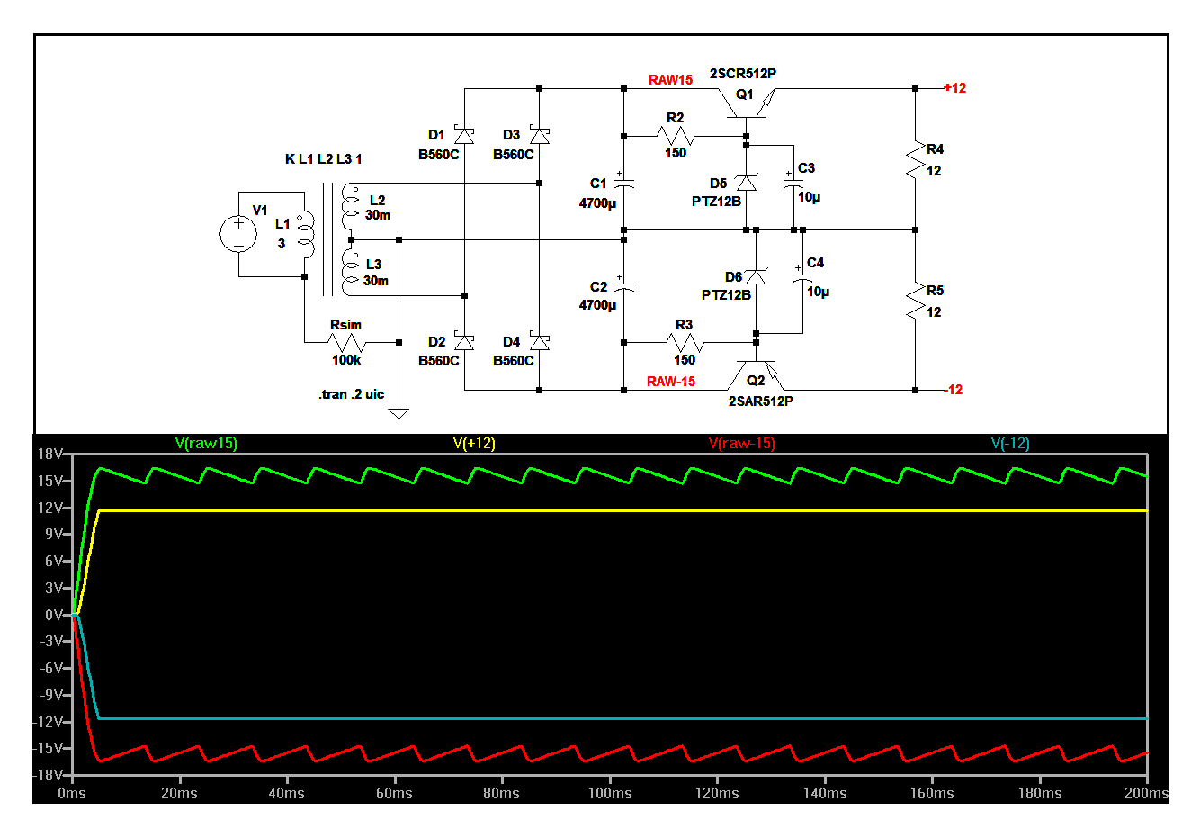
The devil's in the details though, so here's an LTspice schematic and circuit list so you can simulate the circuit and play around with it if you want to get a better handle on what's actually going on in there. I don't have 7812 and 7912 models in my library, so I cheated a little and made the regulators out of discretes.

Version 4
SHEET 1 992 680
WIRE 208 -256 80 -256
WIRE 352 -256 208 -256
WIRE 432 -256 352 -256
WIRE 512 -256 432 -256
WIRE 848 -256 608 -256
WIRE 896 -256 848 -256
WIRE 80 -208 80 -256
WIRE 208 -208 208 -256
WIRE 352 -176 352 -256
WIRE 400 -176 352 -176
WIRE 560 -176 560 -192
WIRE 560 -176 480 -176
WIRE 848 -176 848 -256
WIRE 560 -160 560 -176
WIRE 640 -160 560 -160
WIRE 352 -128 352 -176
WIRE 560 -128 560 -160
WIRE 640 -128 640 -160
WIRE 208 -96 208 -144
WIRE 208 -96 -112 -96
WIRE -192 -80 -304 -80
WIRE -304 -48 -304 -80
WIRE -192 -48 -192 -80
WIRE 352 -16 352 -64
WIRE 560 -16 560 -64
WIRE 560 -16 352 -16
WIRE 576 -16 560 -16
WIRE 640 -16 640 -64
WIRE 640 -16 576 -16
WIRE 656 -16 640 -16
WIRE 848 -16 848 -96
WIRE 848 -16 656 -16
WIRE -112 0 -112 -16
WIRE -32 0 -112 0
WIRE 352 0 352 -16
WIRE 352 0 -32 0
WIRE -112 16 -112 0
WIRE 576 32 576 -16
WIRE 656 32 656 -16
WIRE 352 48 352 0
WIRE -304 64 -304 32
WIRE -192 64 -192 32
WIRE -192 64 -304 64
WIRE 848 64 848 -16
WIRE -160 96 -160 -96
WIRE -144 96 -144 -96
WIRE 80 96 80 -144
WIRE 80 96 -112 96
WIRE 80 144 80 96
WIRE 208 144 208 -96
WIRE 576 160 576 96
WIRE 656 160 656 96
WIRE 656 160 576 160
WIRE -192 176 -192 64
WIRE -160 176 -192 176
WIRE -32 176 -32 0
WIRE -32 176 -80 176
WIRE 352 176 352 112
WIRE 416 176 352 176
WIRE 576 176 576 160
WIRE 576 176 496 176
WIRE 576 192 576 176
WIRE 80 256 80 208
WIRE 208 256 208 208
WIRE 208 256 80 256
WIRE 352 256 352 176
WIRE 352 256 208 256
WIRE 432 256 352 256
WIRE 528 256 432 256
WIRE 848 256 848 144
WIRE 848 256 624 256
WIRE 896 256 848 256
WIRE -32 288 -32 176
FLAG -32 288 0
FLAG 896 -256 +12
FLAG 896 256 -12
FLAG 432 -256 RAW15
FLAG 432 256 RAW-15
SYMBOL ind2 -208 48 M180
WINDOW 0 -33 73 Left 2
WINDOW 3 -29 39 Left 2
SYMATTR InstName L1
SYMATTR Value 3
SYMATTR Type ind
SYMATTR SpiceLine Rser=1
SYMBOL ind2 -96 112 R180
WINDOW 0 -36 69 Left 2
WINDOW 3 -47 41 Left 2
SYMATTR InstName L3
SYMATTR Value 30m
SYMATTR Type ind
SYMBOL ind2 -96 0 R180
WINDOW 0 -42 65 Left 2
WINDOW 3 -51 40 Left 2
SYMATTR InstName L2
SYMATTR Value 30m
SYMATTR Type ind
SYMBOL schottky 96 -144 R180
WINDOW 0 48 33 Left 2
WINDOW 3 24 0 Left 2
SYMATTR InstName D1
SYMATTR Value B560C
SYMATTR Description Diode
SYMATTR Type diode
SYMBOL schottky 96 208 R180
WINDOW 0 48 33 Left 2
WINDOW 3 24 0 Left 2
SYMATTR InstName D2
SYMATTR Value B560C
SYMATTR Description Diode
SYMATTR Type diode
SYMBOL res -64 160 R90
WINDOW 0 0 56 VBottom 2
WINDOW 3 32 56 VTop 2
SYMATTR InstName Rsim
SYMATTR Value 100k
SYMBOL schottky 224 -144 R180
WINDOW 0 48 33 Left 2
WINDOW 3 24 0 Left 2
SYMATTR InstName D3
SYMATTR Value B560C
SYMATTR Description Diode
SYMATTR Type diode
SYMBOL schottky 224 208 R180
WINDOW 0 48 33 Left 2
WINDOW 3 24 0 Left 2
SYMATTR InstName D4
SYMATTR Value B560C
SYMATTR Description Diode
SYMATTR Type diode
SYMBOL polcap 336 -128 R0
WINDOW 0 -42 33 Left 2
WINDOW 3 -60 67 Left 2
SYMATTR InstName C1
SYMATTR Value 4700µ
SYMBOL polcap 336 48 R0
WINDOW 0 -41 34 Left 2
WINDOW 3 -60 65 Left 2
SYMATTR InstName C2
SYMATTR Value 4700µ
SYMBOL res 496 -192 R90
WINDOW 0 0 56 VBottom 2
WINDOW 3 32 56 VTop 2
SYMATTR InstName R2
SYMATTR Value 150
SYMBOL npn 512 -192 R270
WINDOW 0 54 31 VRight 2
WINDOW 3 89 -13 VRight 2
SYMATTR InstName Q1
SYMATTR Value 2SCR512P
SYMBOL pnp 528 192 M90
WINDOW 0 49 63 VLeft 2
WINDOW 3 85 113 VLeft 2
SYMATTR InstName Q2
SYMATTR Value 2SAR512P
SYMBOL res 512 160 R90
WINDOW 0 0 56 VBottom 2
WINDOW 3 32 56 VTop 2
SYMATTR InstName R3
SYMATTR Value 150
SYMBOL res 832 -192 R0
SYMATTR InstName R4
SYMATTR Value 12
SYMBOL res 832 48 R0
SYMATTR InstName R5
SYMATTR Value 12
SYMBOL zener 576 -64 R180
WINDOW 0 49 30 Left 2
WINDOW 3 24 0 Left 2
SYMATTR InstName D5
SYMATTR Value PTZ12B
SYMBOL zener 592 96 R180
WINDOW 0 39 31 Left 2
WINDOW 3 24 0 Left 2
SYMATTR InstName D6
SYMATTR Value PTZ12B
SYMBOL polcap 624 -128 R0
SYMATTR InstName C3
SYMATTR Value 10µ
SYMBOL polcap 640 32 R0
SYMATTR InstName C4
SYMATTR Value 10µ
SYMBOL voltage -304 -64 R0
WINDOW 3 24 96 Invisible 2
WINDOW 123 0 0 Left 2
WINDOW 39 0 0 Left 2
SYMATTR InstName V1
SYMATTR Value SINE(0 170 50)
TEXT -224 -136 Left 2 !K L1 L2 L3 1
TEXT -168 264 Left 2 !.tran .2 uic


