3
\$\begingroup\$

I'm hoping someone here has some experience with the PCA 9685 PWM controller (16 channel, I2c interface). So far everything is working pretty well after getting the circuit connected properly. I'm using a Picobuck LED driver to drive this high power RGB LED.

The PCA9685 allowed for a PWM frequency of between 40Hz and about 1500Hz. The default is 200Hz. After setting this frequency, I can choose the pulse on and pulse off interval anywhere from 0-4096 (which is the pulse resolution). So if I want the LED on full brightness, I can set On=0 and Off=4095. This works fine and I get a nice solid LED.

However if I start to dim one of the LEDs to say 25% of it's brightness, I'll set the On=0, Off=1000. This dims the LED but sometimes it starts to flicker. I've tried a lot of different combinations of On/Off times and PWM frequencies. Even at 1000Hz it is flickering, and it gets worse when I start to use all 3 RGB components.

I'm driving the Picobuck with a seperate 12V DC source, and it has a heatsink. Do I need a resistor or a capacitor somewhere in the circuit to stop the flickering? All I'm trying to do is get the LED dimmable from 0-100% without any flicker, so I can combine the red, green and blue colors.

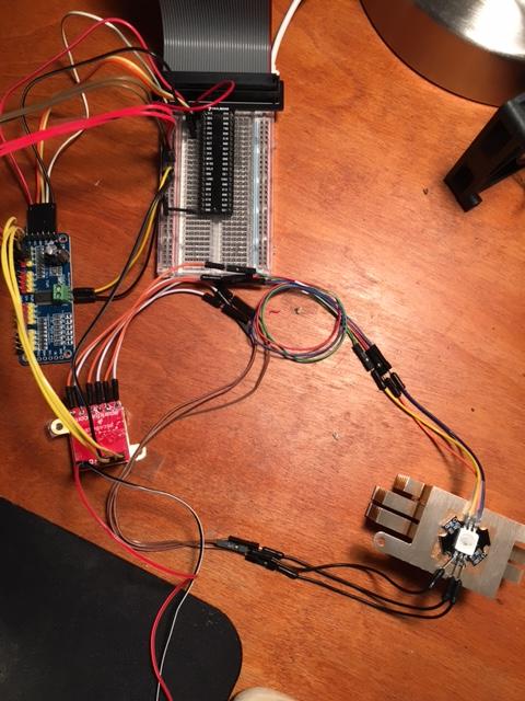
Here is a picture of the setup, there are no extra components - just PCA9685 board, Picobuck and the RGB LED. The red/black wires off the Picobuck are going to a seperate 12V DC supply.

enter image description here What am I doing wrong?

\$\endgroup\$
9
  • \$\begingroup\$ Some pictures of the experimental setup would be helpful. You might try shortening your wires and measuring a few voltages and waveforms for us. \$\endgroup\$
    – Daniel
    Commented Feb 19, 2016 at 19:11
  • \$\begingroup\$ @Daniel I added a photo of the setup I have. From everything I've read on the PCA9685 this is how it should be setup. The Picobuck just drives the LEDs based on a PWM value. It almost works, brightness works, color works just sometimes there is a flicker. \$\endgroup\$
    – Jon
    Commented Feb 20, 2016 at 0:24
  • \$\begingroup\$ It's hard to tell much, but you might want to move your ground to the PicoBuck from the Raspberry Pi breakout to the PWM breakout. If your high-power supply is not isolated, you need to consider how that may influence things too. \$\endgroup\$
    – Daniel
    Commented Feb 20, 2016 at 1:45
  • 1
    \$\begingroup\$ Those are some LONG LEADS ... the longer the wire & the more 'loops' in it, the higher the wire's inductance (resistance to changing currents). In addition to the 2 resistors & 2 transistors per LED in the circuit from my answer, you might want to shorten those wires (most important being the wires from PWM to PicoBuck) & maybe add a capacitor to each LED output from the picobuck. \$\endgroup\$ Commented Feb 20, 2016 at 2:49
  • 2
    \$\begingroup\$ Found some more info and managed to solve my problem by turning off phase balancing. This may have other implications, but for now it suits my purposes. See my new answer below. \$\endgroup\$
    – pcdev
    Commented Apr 11, 2018 at 13:54

3 Answers 3

4
\$\begingroup\$

I've had the same problem as the OP and found this post on the NXP forums which describes my problem (and I think the OP's problem?) well. In any case this ESE page is one of the first sites that appears when searching for PCA9685 flickering LEDs, so I thought I'd add my solution here. From the NXP forum:

Looking at the datasheet (http://www.nxp.com/docs/en/data-sheet/PCA9685.pdf) fig. 11 on page 20 this looks according to design, the problem is whenever LEDn_ON > LEDn_OFF and the LEDn_OFF register is updated, the device skips one whole output phase, switching the output off regardless of the registers -- look at the empty cycle between "register(s) updated in this cycle" and "output(s) updated in this cycle". There's no empty cycle when LEDn_ON < LEDn_OFF as seen on fig. 10 on the preceding page.

So it isn't an electrical problem, or a problem with the Picobuck (I'm using plain old MOSFETs), it's a problem with the PCA9685 chip itself: keeping the output off for (the remainder of?) a cycle whenever the duty is changed if certain register conditions are met, and if the rising edge is not synchronised with the chip's internal timer.

This poster's final comment was:

Is there a way to avoid this kind of behavior and still benefit from output load balancing?

Spoiler alert: as of writing this there is no answer yet - But this lead me to investigate and try turning off whatever this "load balancing" thing is. I'm using this library for driving it, and after scouring the source I tried changing the declaration of the PCA9685 object found in the sample from this:

PCA9685 pwmController;

to this:

PCA9685 pwmController(Wire, PCA9685_PhaseBalancer_None);

And... Smooth as butter!

So what is load balancing, and why should I care?

Well, it appears to be a way to stagger the rising edge of the PWM signal across each channel, presumably to ease the instantaneous current changes of all 16 channels rising at once and potentially falling at once if the brightness/duty of each channel is equal. The other options in the library are *_Linear which staggers the waveforms by a fixed delay for each channel from the one before it, *_Weaved which interleaves the delays across channels, "balancing the first few outputs better" (whatever that means) and *_Count which is not implemented by the library and works exactly the same as *_None.

Any staggering of the phase results in flickering as soon as levels are changed, and this may also have an effect on particular duty cycle ranges based on the PWM frequency.

Implications I presume are unstable power draw and stronger EMI. I presume this means power should be buffered with a good sizeable cap, but I'm not sure what to do (if anything) about the potential EMI - is it a problem? Is there another issue to consider with turning off phase balancing? If anyone more technical can comment on this, I'd be most grateful.

\$\endgroup\$
2
  • \$\begingroup\$ I'm using this library for Node.js and there is no phase balance option? github.com/101100/pca9685/blob/master/src/pca9685.ts \$\endgroup\$
    – Jon
    Commented Apr 19, 2018 at 22:23
  • \$\begingroup\$ Hmmmm, interesting I hadn't seen that before. Are you using the same onStep value for all channels (preferably 0)? Which method are you calling to change the duty? Another thing I noticed was that some channels flicker more than others, presumably because they are off for longer during the cycle reset while others don't seem to flicker much at all. Are you noticing that? \$\endgroup\$
    – pcdev
    Commented Apr 19, 2018 at 23:48
3
+25
\$\begingroup\$

From the page you linked for your PicoBuck:

This PicoBuck supports PWM control so long as the signal is above a minimum of ~1.5V and each LED is driven to ~350mA.

What might be happening here is that there is a capacitance (either an intentional cap, or parasitic capacitance...most likely a cap tho) between your square-wave PWM output and the corresponding input to your PicoBuck.

  • When you turn down the duty cycle to get the really low outputs, it can take multiple pulses to sufficiently charge the cap to >=1.5V.
  • This can effectively form another oscillator (similar to a sawtooth osc) where the cap charges for several pulse cycles before reaching the PicoBuck's threshold voltage & 'tripping' the PicoBuck to flash the LED, down to a low enough frequency to cause visible flashing as the duty cycle reaches low enough values.

Possible fixes:

  • If there's an easily removable capacitor on your PWM output, remove it (or at least replace with one of significantly lower value).
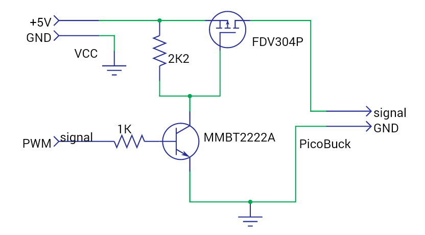
  • Try adding an NPN & a schmitt trigger/P-FET (or an op-amp with high voltage multiplier) between the PWM output & the PicoBuck's input to 'square up' the signal waveform to as close as possible to a clean +5V/0V square wave, low-impedance signal.
    Here's an example using about $2 worth of components per LED: Example Square-Wave Amp

  • Check for supply voltage irregularities in either your PWM controller's supply pins, or the same for the PicoBuck. I suspect that your notice of "it get[ting] worse when [you] use all 3 RGB components" is most likely that it's more noticeable due to proximity/visual comparison, rather that affecting the 'actual' output. However, simce you mentioned it, checking for supply voltage issues would be the first place to look for something that could cause that.

\$\endgroup\$
4
  • \$\begingroup\$ There are no other components in the circuit (see the photo I added). I'm not sure what a Schmitt trigger/P-FET is but I can do some reading and see if that will help. I don't have an oscilloscope to test the square wave with unfortunately. The 12V supply to the Picobuck is steady as far as a multimeter is concerned, but that's all I know. I am from a software background and finally feel what it must be like for the guys asking questions on there! I'm sorry this is quite new to me, I'm a beginner with electronics. \$\endgroup\$
    – Jon
    Commented Feb 20, 2016 at 0:26
  • 1
    \$\begingroup\$ @Mangist a [Scmitt Trigger] (en.wikipedia.org/wiki/Schmitt_trigger) is a digital device that 'triggers' when its analog input rises or falls past a preset threshold; thus turning a slowly changing input voltage to an abrupt on/off square-wave pattern. A [P-FET, P-MOSFET, or P-Channel FET/MOSFET] (en.wikipedia.org/wiki/MOSFET) is a type of transistor that's often used as a 'solid state switch' in circuits; when its 'gate' pin voltage is pulled low with respect to the source pin. I'll add a quick circuit diagram to my answer to help a bit. \$\endgroup\$ Commented Feb 20, 2016 at 2:00
  • \$\begingroup\$ @Mangist any updates for us, or are you stuck waiting for parts to ship? \$\endgroup\$ Commented Feb 20, 2016 at 21:15
  • \$\begingroup\$ The whole point of using the Picobuck was to eliminate the need for additional circuitry. It's supposed to just drive the LEDs based on PWM input. I may have to try and build that circuit above and see if it stops the flickering. I will try and check the supply voltage using my multimeter, but I don't have an oscilloscope. I will change to using a 9V battery which will be more stable. \$\endgroup\$
    – Jon
    Commented Feb 24, 2016 at 21:33
1
\$\begingroup\$

Reading the datasheet for AL8805 (the chip in PicoBuck) there's two modes of controlling it: either PWM or a constant control voltage. It's possible that the flickering happens because the chip gets confused which one you're trying to do.

Couple of troubleshooting things to try:

  1. Try the constant control approach: instead of using the PWM driver, whip up 1 V with a voltage divider and use it as the PicoBuck input.
  2. How fancy is your multimeter? If it has hold settings for min/max voltage, stick it between GND and IN1 of the PicoBuck and check that the minimum voltage is low enough and the maximum is high enough (see Recommended Operating Conditions in the datasheet). And if it's got True RMS, measure the average voltage to see if it's in the right ballpark.

Experimental: If the constant voltage control works and you can't make PWM work, stick a whooping big capacitor between PicoBuck input and ground, and maybe a small resistor for current limiting. The idea is to smooth the PWM signal into a corresponding control voltage. Disclaimer: Untested, might fry the PWM controller. Looking at the datasheet it looks unlikely but proceed with caution.

The datasheet for reference: http://cdn.sparkfun.com/datasheets/Components/LED/AL8805.pdf

\$\endgroup\$
4
  • \$\begingroup\$ I'm not sure how to whip up 1V with a voltage divider. I am just using the PWM method based on the PCA9685 outputting a PWM @ 3.3V. That should be more than the 1.5V threshold for the Picobuck to accept it as a PWM input. My multimeter doesn't have those min/max functions, but I do have access to an oscilloscope, except the guy who knows how to use it is away. I'm going to try what you suggest and put a large capacitor between Picobuck and GND. Any suggestion on uF? Wouldn't the capacitor smooth out the PWM signal and defeat the point of using PWM? \$\endgroup\$
    – Jon
    Commented Feb 24, 2016 at 21:35
  • \$\begingroup\$ A voltage divider is a simple thing: put two resistors in series between ground and 3.3 V. The voltage between the resistors is then R1/(R1+R2). I'm suggesting it to try to narrow down the source of the problem. If it still keeps flickering, the problem is then in the PB or the LED. \$\endgroup\$
    – lrasinen
    Commented Feb 25, 2016 at 6:16
  • 1
    \$\begingroup\$ An oscilloscope is even better. For the capacitor, let's do some math. Let's say the frequency you have is 1000 Hz and we're willing to allow for a 5% ripple. That means the RC time constant T = RC should be such that exp(-0.001 / T) > 0.95. Since log(0.95) is roughly -0.05, we get 0.001 / T < 0.05 and solving for T gets us T > 0.02. So try for example 1 kOhm resistor and a 22uF cap in series. Or 100 ohms and 220 uF. Whatever you have handy in that ballpark. \$\endgroup\$
    – lrasinen
    Commented Feb 25, 2016 at 6:30
  • \$\begingroup\$ Are you saying put a capacitor and resister in series, and then attach these between the Picobuck input pin and ground? Like PWM----Cap----Resistor----Gnd ? \$\endgroup\$
    – Jon
    Commented May 3, 2016 at 20:15

Your Answer

By clicking “Post Your Answer”, you agree to our terms of service and acknowledge you have read our privacy policy.

Not the answer you're looking for? Browse other questions tagged or ask your own question.