2
\$\begingroup\$

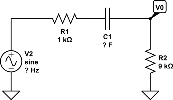
schematic

simulate this circuit – Schematic created using CircuitLab

What is the smallest value of C that will ensure that the 3dB frequency is not greater than 100Hz?

That is the question from the book but my question is not that exactly.

I am trying to find the cutoff frequency which is of course a step toward the solution and I have the transfer function:

$$\frac{sC_1R_2}{sC_1(R_1+R_2)+1}$$

now somehow the book goes straight from the transfer function to

$$\omega_0 = \frac{1}{C_1(R_1+R_2)}$$

I am having trouble understanding how we found \$\omega_0\$.

\$\endgroup\$
2
  • \$\begingroup\$ Can you please point out the Vout "node" you used to calculate the transfer function (assuming your transfer function is Vout/V2)? Is it over R2? \$\endgroup\$ Commented Feb 12, 2016 at 17:52
  • \$\begingroup\$ Yes sorry. Its been added \$\endgroup\$
    – user125621
    Commented Feb 12, 2016 at 17:55

3 Answers 3

2
\$\begingroup\$

The rolloff frequency of a R-C filter is:

  F = 1 / (2πRC)

When R is in Ohms, C in Farads, then F is in Hz.

Therefore to get the capacitance:

  C = 1 / (2πFC) = 1 / [2π(100 Hz)(10 kΩ)] = 160 nF

Yes, it's really that easy.

R-C rolloff filter calculations come up a lot in electronics. I keep 1/2π permanently in a register in my calculator. I can then divide that by two of the frequency, capacitance, or resistance to get the third.

\$\endgroup\$
4
\$\begingroup\$

From the transfer function, I ended at a rather interesting answer:

$$H(j\omega) = \frac{j \omega C_1 R_1}{j \omega C_1 (R_1 + R_2) + 1}$$

$$abs(H) = \frac{\omega C_1 R_1}{\sqrt{\left(\omega C_1 (R_1 + R_2)\right)^2 + 1}}$$

Finding cutoff frequency (step by step, so we don't trip):

$$\frac{\omega_0 C_1 R_1}{\sqrt{\left(\omega_0 C_1 (R_1 + R_2)\right)^2 + 1}} = \frac{1}{\sqrt{2}}$$

$$\frac{(\omega_0 C_1 R_1)^2}{\left(\omega_0 C_1 (R_1 + R_2)\right)^2 + 1} = \frac{1}{2}$$

$$(\omega_0 C_1 R_1)^2 = \frac{\left(\omega_0 C_1 (R_1 + R_2)\right)^2 + 1}{2}$$

$$(\omega_0 C_1 R_1)^2 - \frac{\left(\omega_0 C_1 (R_1 + R_2)\right)^2}{2} = \frac{1}{2}$$

$$(\omega_0 C_1)^2 \left(R_1^2-\frac{\left(R_1 + R_2\right)^2}{2}\right) = \frac{1}{2}$$

$$\omega_0 C_1 = \frac{1}{\sqrt{2\left(R_1^2-\frac{\left(R_1 + R_2\right)^2}{2}\right)}}$$

$$\omega_0 C_1 = \frac{1}{\sqrt{2\left(R_1^2-\frac{R_1^2 + 2R_1R_2 +R_2^2}{2}\right)}}$$

$$\omega_0 = \frac{1}{C_1\sqrt{R_1^2-2R_1R_2-R_2^2}}$$

I did not reach your book's very-well known formula, yet seemingly incorrect for this application. I could only bet the one who wrote the solution just botched it. Or I did. Eitherway, there's my two cents.
\$\endgroup\$
3
  • 2
    \$\begingroup\$ Your solution is almost on the right track; the filter has some built-in attenuation (in this case -20dB), so the right hand side should be modified to be \$\frac{R_1}{(R_1+R_2)\sqrt{2}}\$. \$\endgroup\$ Commented Feb 12, 2016 at 19:56
  • \$\begingroup\$ Using a CAS program with this slight modification I do indeed get the book's solution, which also matches a Bode plot solution for \$V_o\$. \$\endgroup\$ Commented Feb 12, 2016 at 19:59
  • \$\begingroup\$ @helloworld922 Can you possibly elaborate on how you came up with the modified part? \$\endgroup\$
    – user125621
    Commented Feb 13, 2016 at 4:57
3
\$\begingroup\$

For this type of a circuit the cutoff frequency is not at Vin/Vin = 0.707. Because the R1 and R2 form a voltage divider, and "mid-band gain" (maximum of Vout) is equal to R2/(R1 + R2) = 0.9[V/V], therefore the cutoff frequency is at 0.9*0.707 = 0.636(the frequency at where the magnitude of Vout is 3dB less than the maximum of Vout).

And this is why right hand side of the equation should looks like this: $$\frac{R2}{R1+R2}*\frac{1}{\sqrt{2}}=\frac{R2}{(R1+R2)\sqrt{2}}$$

$$\frac{\omega_0 C_1 R_1}{\sqrt{\left(\omega_0 C_1 (R_1 + R_2)\right)^2 + 1}} = \frac{R2}{(R1+R2)\sqrt{2}}$$.

But there is a simpler method for finding the cutoff frequency. 1 - Finding the pole directly from transfer function

$$H(s)=\frac{sC_1R_2}{sC_1(R_1+R_2)+1}$$

And for this type of a circuit we can do it by inspection.

2 - We can find a time constant of the circuit. In this case the time constant is \$\ t=C1*(R1+R2)\$ and \$\ \Large Fc =\frac{1}{2*\pi * t} \$

\$\endgroup\$

Your Answer

By clicking “Post Your Answer”, you agree to our terms of service and acknowledge you have read our privacy policy.

Not the answer you're looking for? Browse other questions tagged or ask your own question.