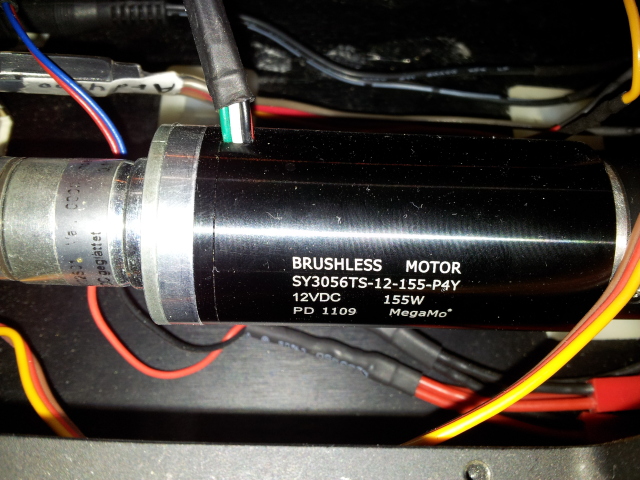
I have this a MegaMo SY3056 BLDC Spec.PDF

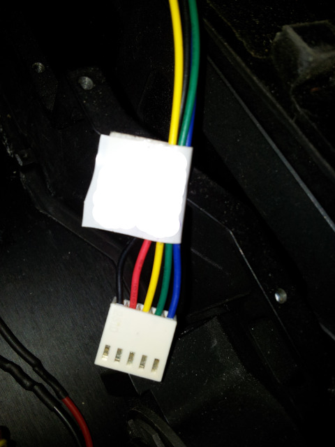
And beside the cables that are connected to the ESC i have thses encoder cables:

How can i read this encoder? and what values do i get?
Can i know the absolut position of the motor ?
I have this a MegaMo SY3056 BLDC Spec.PDF

And beside the cables that are connected to the ESC i have thses encoder cables:

How can i read this encoder? and what values do i get?
Can i know the absolut position of the motor ?
I found a data sheet for a different MegaMo motor. It seems to have similar wiring, with the following specs related to the encoder connector:
A Hall Sensor         Blue
B Hall Sensor         Green
C Hall Sensor         Yellow
+6V Logical Supply    Red
GND Logical           Black
(from the BL2235 datasheet)
This should at least get you started on reading the encoder. Couldn't find anything more detailed about the sensors/resolution. Hopefully you find this helpful.
With no proper datasheet available looks like you will have to guess (I had a look, very little on the website - you could try sending an email to the address given there)
Is there an encoder attached to the motor also? How many wires are coming from the motor in total?
A few thoughts...
If the wires going into the casing in the top picture are the main motor connections:
I think the red is for V+, black for ground. This is easily confirmed by briefly applying power and see if the motor turns.
The other three(?) are likely to be for the hall effect sensor - possibly white for V+, green for ground and [unseen wire] for output.
It would be wise to use a current limited supply if you have one (e.g. bench supply)
If not I would put a 100-500 ohm resistor in series with the V+ to the sensor (whichever wire you are trying)
The sensor output may be open drain, so a 1-10k resistor from the output to V+ maybe required.
Not sure about the encoder wires without more info.
More photos/explanation of wiring/electronics (can you partially dismantle to get a better look if necessary?) might help to guess better.