6
\$\begingroup\$

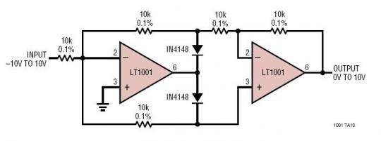
I'm trying to figure out how this circuit works:

enter image description here

It is a absolute value circuit; that is, the output follows the absolute value of the input. In the process of figuring out how it works, I am imagining a positive input voltage. If this is the case, then the first op-amp acts as an inverter, so the voltage above the diode is the negative of the input. So, I understand how the first part works. I then get stuck on the second part: The voltage at the non-inverting input to the second op-amp is Vin since no current flows through the lower resistor. If this is true, then the second op-amp tries to make the inverting input also equal to Vin. If it achieves this, then there is a voltage drop of 2Vin across the input resistor to the second op-amp, and hence a current of Vin/5000 flows through the feedback resistor. There is a voltage drop of 2Vin across the feedback, so the output voltage is either -Vin or 3Vin.

Can you please pick apart my logic and tell me why I'm wrong? I've been trying to puzzle it out for ages but I can't see the solution.

\$\endgroup\$
1
  • \$\begingroup\$ hint: assume there is negative feedback for the first op amp, the inverting input must then be at 0V because the non inverting is grounded. Now if Vin is positive current flows from L to R in the first resistor, if it is negative it flows from R to L. Split the cases, try to understand which diode is on and you should get the solution. \$\endgroup\$ Commented Feb 17, 2016 at 22:53

1 Answer 1

11
\$\begingroup\$

The left op-amp is working in inverting mode.

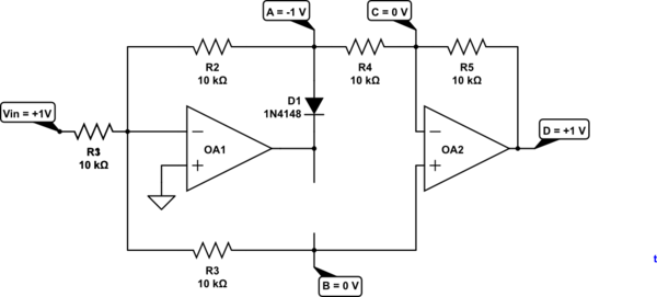
schematic

simulate this circuit – Schematic created using CircuitLab

Figure 1. Positive going input.

  • If the INPUT voltage goes positive then the - input will start to rise above the + input and the output will start to go negative.
  • D1 will then conduct pulling the - input back down to zero.
  • The voltage on R2/R4 junction will be -Vin.
  • The voltage on OA2 + input will be 0 V since it's tied to the virtual zero of OA1.
  • OA2 is then operating in inverting mode so the output will be -(-Vin) = Vin.

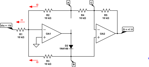
schematic

simulate this circuit

Figure 2. Negative going input.

  • When the INPUT voltage goes negative the cleverness of the circuit comes into play.
  • OA1 - input will be virtual zero so I1 = 0.1 mA.
  • If OA2 is in equilibrium both inputs will be at the same voltage. Therefore \$V_B = V_C\$.
  • Since there is 20k in the upper circuit and only 10k in the lower circuit \$i_3 = \frac{2}{3}I_1\$.
  • Therefore \$V_B = -\frac {2}{3}V_{IN}\$ as is \$V_C\$.
  • OA2 is then operating in non-inverting mode so the output $$ V_{D} = V_B (1 + \frac {R_f}{R_i}) = V_B (1 + \frac {10k}{20k}) = 1.5 \cdot V_B = 1.5\cdot\frac{2}{3}(-V_{IN}) = -V{IN} $$

It took me a while to see what was happening. I hope that helps.

\$\endgroup\$
2
  • \$\begingroup\$ Looks correct!! \$\endgroup\$
    – beeedy
    Commented Feb 17, 2016 at 23:02
  • \$\begingroup\$ Thank you very much indeed. I completely missed the fact that the + input of OA2 is tied to OA1's virtual earth, which obviously screwed up the rest of my puzzling. \$\endgroup\$
    – imulsion
    Commented Feb 17, 2016 at 23:05

Your Answer

By clicking “Post Your Answer”, you agree to our terms of service and acknowledge you have read our privacy policy.

Not the answer you're looking for? Browse other questions tagged or ask your own question.