1
\$\begingroup\$

I am looking for a solution to modulate a data signal into a DC powerline that has 12-60V. I found for example the DC-Bus solution from Yamar. But they are the only ones offering this and their chips are 5$+; even in high quantities. That's too much.

I read somewhere that I could use a coupling capacitor. But then I whoud still need to know how to it like that and how I modulate it best (I know what a coupling cap is tho; even tho I don't really get how I would do that yet)

If there is an easy and cheap solution to implement without a full IC, I am glad to hear about it too :)

Any advice is appreciated, even if it's just Kewords I can google about.

The data rate should be in the kbps range. Mbps is nice but by no means needed!

And yes, there is really only that way of doing it. RF is no option and additional wires too.

Edit1:

The data I want to transmit is a voltage of a solar panel every few seconds. So as you can see, the data is not very vital and if I wanted to increase reliability I could just transmit the voltage twice.

Because multiple panels are in series , I thought of a master that announces which panel can "speak" next.

I thought maybe it's easiest if there is like two different frequency levels. one for the master to say whos turn it is and one for the actual voltage. So e.g: base indicating frequency is 100khz. Each khz more is +1. so if the master modulates in 100kz that means panel 0 should speak, 101khz means panel 1 etc. Same would go for VTG: base frequency could be 10khz and each additional khz could means +1. so eg. 12V is 10khz, 13V is 11khz etc.

I don't know how stupid or difficult that actually is compared to serial methods :)

I used RS232 for a lot of projects yet even tho I wouldn't say I understand the protocol itself to it's farest extents. I would say I know the basics (+3 is logical zero, -3 is logical 1, There is a start bit synchronizing the clock and a stop bit I don't understand exactly what it is for other than a minimum of one bit pause between two bytes :).

Thanks in Advance!

\$\endgroup\$
6
  • \$\begingroup\$ How many things are connected to the DC powerline? Do you have design control over all of the devices, or if not, would you be able to install filters on the DC input to all devices? The problem I am considering is controlling the AC impedance on the powerline so that you can drive an AC signal onto it without a large current requirement. \$\endgroup\$
    – user57037
    Commented Mar 3, 2016 at 21:05
  • \$\begingroup\$ Yes, I can design it however I want to. The only limitation is that i can only use the DC powerline to communicate. \$\endgroup\$
    – Yatekii
    Commented Mar 3, 2016 at 22:28
  • \$\begingroup\$ Right. Why not just have one-way communication? Get the controller at the panels to periodically transmit back, in sequence, each panel number followed by the voltage and a checksum. Will all the panels be connected to the one transmitter? \$\endgroup\$
    – Transistor
    Commented Mar 3, 2016 at 23:12
  • \$\begingroup\$ you mean if they are all connected to one receiver? Or do I misunderstand you? Every panel has a sensor and they all report back to one central unit :) If they report back in sequence they would all need to know their predecessor. This would make comms easy but make production more complicated because their IDs would have to be in series or programmed at the point of installation. If the protocol is strict (slave only talks after the master allowed it), having bidirectional comms shouldn't be an issue no? \$\endgroup\$
    – Yatekii
    Commented Mar 3, 2016 at 23:26
  • 1
    \$\begingroup\$ Bi-direction comms will be more than twice as complicated. All this info should have been in the original question. What else is missing? Is this a commercial application? \$\endgroup\$
    – Transistor
    Commented Mar 3, 2016 at 23:36

1 Answer 1

3
\$\begingroup\$

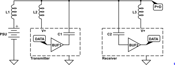
This approach is common in industrial control systems such as AS-i.

schematic

simulate this circuit – Schematic created using CircuitLab

Figure 1. Power and data on the same wire.

Here is a simple idea that meets your criteria and might even work!

  • Problem 1 is to make the DC circuit high impedance to your data signal. This can be achieved by adding a series inductor to each power feed and tap-off. You need to calculate the inductance based on the frequency of your data signal and how low an impedance your data signal can drive and still be readable by the receiver.
  • Problem 2 is to superimpose the data signal on the line. AC coupling should suffice for that. Again, you need to calculate the capacitor value based on the data frequency and load impedance.

Note that since the transmitter is most likely to be in the same location as the PSU that L2 could be omitted and the transmitter powered directly from the battery.

All loads on the line, including the receivers, will need a capacitor between internal V+ and GND to minimise feeding switching transients back onto the P+D (power + data) line.

You have a bit of work to do but judging by your question you have time but not money. ;^)

\$\endgroup\$
8
  • \$\begingroup\$ Wow, thanks a whole lot! This answer really explains a lot and helps me very much. Not to mention the awesome drawing! Time is really no problem and I am very willing to read a lot too. This all makes sense to me but one thing:How am I supposed to actually put data. I mean, I can do this AM or FM I guess. There is also PSK. AM is the easiest but I am concerned because I do not know what exact VDC I have. It could change over time (with very low frequency!!) so I would need a reference voltage I guess. I thought of maybe a cap that buffers the level whilst the transmission goes on? \$\endgroup\$
    – Yatekii
    Commented Mar 3, 2016 at 22:22
  • \$\begingroup\$ Sorry for the long followup that doesn't even fit into 600 chars ... I hope that's ok! Would you rather do FM or PSK than AM? I really don't need a high data rate but I need kind of a high range (40-50m). That's kind of the thing that troubles me most atm. How do I determine the range I can get. Because I know of SPI and TWI that really suck on high ranges :) \$\endgroup\$
    – Yatekii
    Commented Mar 3, 2016 at 22:22
  • \$\begingroup\$ How much data do you need to transmit and how much pain would you suffer if there was an error? i.e., Are you just switching stuff like lights on and off remotely every once in a while or are you building an autonomous fly-by-wire car that will carry you and your family in high-speed traffic? Edit your original question with the additional info - bits per second, or whatever - and you might get a better response than mine. Also indicate what level of understanding you have of serial data transmission such as RS232 or RS485 because your data will be similar. \$\endgroup\$
    – Transistor
    Commented Mar 3, 2016 at 22:36
  • \$\begingroup\$ I answered your followup question in the edit. Satisfactory I hope :) \$\endgroup\$
    – Yatekii
    Commented Mar 3, 2016 at 22:55
  • \$\begingroup\$ FSK is also a possibility (maybe you consider FSK to be a type of PSK). If you organize your system so that it always changes frequency at zero crossings, the phase will be continuous, which is a good thing. \$\endgroup\$
    – user57037
    Commented Mar 3, 2016 at 23:08

Your Answer

By clicking “Post Your Answer”, you agree to our terms of service and acknowledge you have read our privacy policy.

Not the answer you're looking for? Browse other questions tagged or ask your own question.