5
\$\begingroup\$

I put a reed switch ( https://en.wikipedia.org/wiki/Reed_switch ) on the handle of a measuring wheel (perambulator). The reed switch will be activated up to around 20 times per second (every 50 ms). The sampling rate on my data acquisition is 200 Hz (every 5 ms). The DAQ is made with an IOIO OTG ( https://en.wikipedia.org/wiki/IOIO ) and the analog input I use can handle (0-3) V. Should I go for a Schmitt trigger or do you have a more elegant solution on how to have a long enough output signal from the reed switch to safely sample it?

I am only interested in the time between activations of the reed switch. I plan to put a LED and a beeper to get a short noise and a flash of light for each. The input level to the IOIO OTG will be the 0.7 V due to the LED. There are 9 mm diameter neodymium magnets mounted on the wheel and the wheel has a circumference of 1 m. I put 10 magnets on the wheel and the approximately highest speed I will measure is 2 m/s. Then the wheel rotates twice per second and thus I have up to around 20 activations of the reed switch per second.

Since we know the circumference of the wheel (1 m) and the 10 magnets are evenly spread out, knowledge of the time between activation of the reed switch will give a good approximation of the speed.

Edit: Changed the text regarding the placement of the reed switch. The reed switch is next to the wheel and the 10 magnets are on the wheel. I want to have 10 magnets to get a good estimation of the walking speed of the person holding the measuring wheel.

I guess I could use a digital input instead. I didn't consider it would be a better option in this case.

Maybe I should clarify what I mean about 1 m circumference and 10 magnets. Between every reed switch output the wheel has travelled 10 cm. If the wheel rotates 2 times per second at fast walking speed (2 m/s) the reed switch will close 20 times per second.

\$\endgroup\$
10
  • 2
    \$\begingroup\$ I'd use a one-shot triggered by the switch contact closure/opening, but I'm confused... If the magnets are on the wheel and the switch is also on the wheel, how does the switch get actuated? \$\endgroup\$
    – EM Fields
    Commented Mar 16, 2016 at 10:26
  • 3
    \$\begingroup\$ Why are you using an analog input? The relay has 2 states that you are interesting in, open and closed. Use a digital input, its a lot easier, and then you will not be restricted to a 200Hz sampling rate. Also, why 10 magnets? Surely 1 is enough to tell the speed. If you need to extend the pulse output of the reed switch then a simple RC circuit will do that. \$\endgroup\$
    – Steve G
    Commented Mar 16, 2016 at 10:43
  • \$\begingroup\$ I have edited the text in response to your comments. I want a ridiculously good estimation of walking speed since this will be a reference system. \$\endgroup\$
    – phell
    Commented Mar 16, 2016 at 22:54
  • \$\begingroup\$ This sounds nutty. Where is walking speed measured? The hips, the head, shoulders? If the measuring wheel is hand-held at a constant angle and the arm held fairly rigidly then you might be measuring shoulder speed. I think it's meaningless other than, perhaps, to analyse posture - think John Cleese walking with knees bent, shoulders level but legs going everywhere. What are you really trying to measure? \$\endgroup\$
    – Transistor
    Commented Mar 16, 2016 at 23:18
  • \$\begingroup\$ @transistor: I was thinking of having it mounted behind the person who I want to measure the walking speed on. Maybe with two smaller supporting wheels on the sides of the measuring wheel. What I really try to have is a good reference system for measuring the walking speed indoors. GPS will not work and accelerometer based devices are not great for this. \$\endgroup\$
    – phell
    Commented Mar 17, 2016 at 7:38

1 Answer 1

2
\$\begingroup\$

With reed activations for every meter traveled and 200Hz sampling rate, you're effectively limited to 10 m/s in terms of speed you can reliably measure (if you have achieved a perfect 5ms pulse time from the reed). In non-ideal conditions, you should expect reliable operation at about a half of that speed, 5m/s or 18 km/h. Assuming a bicycle application, that's not much.

My point is, you should either increase the sampling rate or reduce the number of magnets you use. The latter is the easiest option, with 2 magnets you'll be able to measure speeds up to 90 km/h, which looks reasonable.

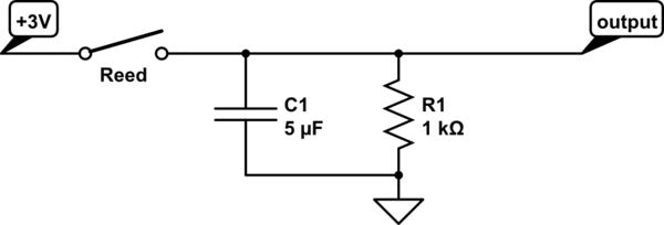
And here's the RC circuit Steve told you about in his comment. It has a time constant of 5ms, so you'll measure between 3 and 1V in the sample following a reed activation, and less that 1V in subsequent samples.

schematic

simulate this circuit – Schematic created using CircuitLab

\$\endgroup\$
1
  • \$\begingroup\$ I upvoted the answer since it is helpful and I had a feeling something like this would be more elegant than a Schmitt trigger. The upvote will show up once I reach a higher status. \$\endgroup\$
    – phell
    Commented Mar 16, 2016 at 22:57

Your Answer

By clicking “Post Your Answer”, you agree to our terms of service and acknowledge you have read our privacy policy.

Not the answer you're looking for? Browse other questions tagged or ask your own question.