It seems you aren't the first person to have this problem.
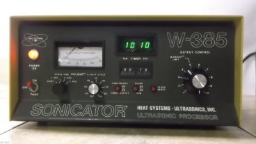
These guys have thought about it and patented a solution.
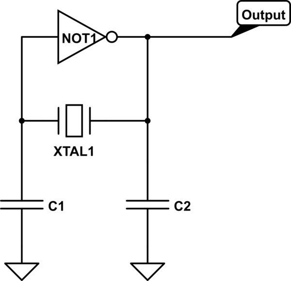
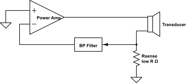
The solution is basically a microprocessor that controls the frequency of the drive signal, and a current detector in the drive circuit.
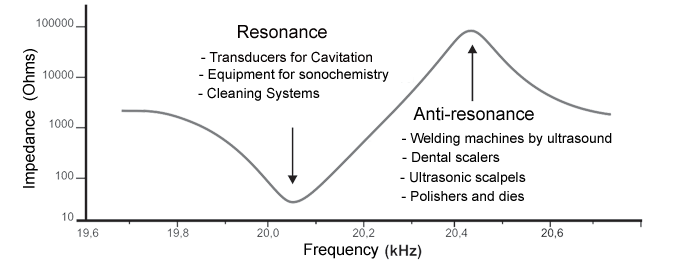
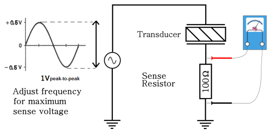
Generate approximately correct signal, then hunt up and down while watching for a maximum of current flow.
You could do this by hand using a multimeter with a small adapter.
You put a current shunt in series with the drive signal ground, then use a small adapter circuit sort of like this:
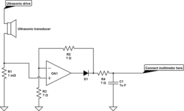
simulate this circuit – Schematic created using CircuitLab
This converts the drive current to a voltage that you can measure with your multimeter.
If you had a multimeter that could measure AC current at the drive frequency of the ultrasonic transducer, you wouldn't need the adapter. But, I don't think there are any multimeters that measure AC current for much above typical powerline frequencies.
The diagram is much simplified and is only intended to show the concept. You may need to use two stages to get enough gain, and the output filter could be made much better.
Given that you mention a 50Ohm drive, you may be up in the MHz range with your ultrasound, so maybe an opamp won't cut it and you'll have to use something better suited to high frequencies instead.
 :
:
