0
\$\begingroup\$

I'm making a voltmeter for the college senior project, and the problem is that voltage divider should equally split 17V into two 9V(nominal value of the batteries. As of now, an actual voltage is 8.5V and eventually will go down as the batteries die, so don't freak out too much by my round errors.) sources, but as soon as I connect Arduino board to the circuit, voltage( across the resistor it's connected to) drops to 2-3 Volts. Which is apparently enough to power the micro controller, but not enough to light the display up. (it's also enough to use the other resistor as a space heater with 14 Volts across it).

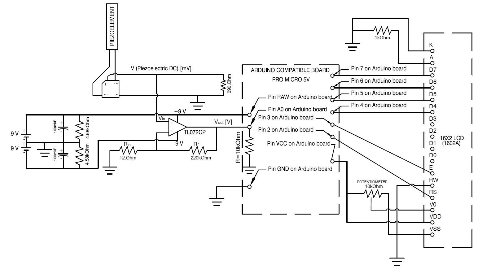
enter image description here

Please feel free to look at the schematic of the device provided above. (either models, or specs of the components are written on the schematic)

Now I'll explain the design thoroughly: The idea is to use piezoelectric element (thin laminated flexible piezoelectric beam), place it into a fluid flow (air) and rectify the outgoing AC signal with a full wave bridge. The next step is to amplify the signal, because it has very low magnitude and arduino analog pin can't register it without amplification.

Amplifier needs at least +-7V supply, so it's provided to it from the two 9V batteries, that are connected to a voltage divider. Therefore, the virtual ground of the circuit is in between the two batteries.

At the same time I want the arduino board (Actually it's not arduino, it's arduino compatible board dubbed Pro Micro 5V) to be powered from the same two batteries.

The whole thing works fine from USB, but from the batteries it works as it pleases!

Here are the design constraints of the device:

  • The entire device shall hang somewhere in a remote location, so it has to be powered from an autonomous power supply (two 9V batteries in my solution).
  • The device should be as light, and as small, as possible. (solutions like adding another battery are not desirable).
  • Arduino board have to have 5V on it to light the display.

Additionally I'd like to learn why micro controller has variable input resistance and what it depends on. I've tried to figure out what is the resistance across the arduino's ground and RAW by assuming that the resistor of the voltage divider and the arduino are connected in parralel. In three different setups I've got the arduino's resistance to be equal to 221.93, 527.73 and 743.4 Ohm. As I understand, the board has some kind of reducer at the voltage input that prevents the board from burning at supplied voltages above 5V and below 12V, but why it drops the supplied voltage from 8V to 2-3V?

\$\endgroup\$
3
  • 2
    \$\begingroup\$ "equally split 17V into two 9V sources" now I know people call me a grumpy old fart, but when exactly did physics change 9+9=17? \$\endgroup\$
    – jippie
    Commented Mar 20, 2016 at 20:08
  • \$\begingroup\$ How does your circuit diagram with the two batteries in it match up with "voltage divider should equally split 17V into two 9V sources"? \$\endgroup\$
    – jippie
    Commented Mar 20, 2016 at 20:15
  • \$\begingroup\$ nominal voltage is 9V, but in fact it's a bit less. 8.5V if you will \$\endgroup\$ Commented Mar 20, 2016 at 20:31

4 Answers 4

10
\$\begingroup\$

You shouldn't power anything from a voltage divider since the output voltage will fluctuate greatly with the amount of current sourced. Rather you should look into a step down voltage regulators. They're inexpensive and will easily triple your battery life.

\$\endgroup\$
1
  • \$\begingroup\$ Thank you for an advice. I'll get one and check if it solves the problem \$\endgroup\$ Commented Mar 20, 2016 at 21:39
5
\$\begingroup\$

The two 4.85K ohm resistors that you picture in your diagram are NOT a voltage divider. They are actually performing no function of value and are in fact putting an unnecessary load on each of the two batteries!!

You have another fundamental issue with the design. The AC to DC bridge rectifier you have in the sensor output path requires a total signal of at least 1.2 to 1.4V amplitude before the output will register anything. If the sensor signal is small you should AC couple it into an amplifier first to gets its level up to well over 1.4V before you try to rectify it.

\$\endgroup\$
2
  • \$\begingroup\$ Oh, I see it too now. They are here because I saw a voltage divider like that on this page tangentsoft.net/elec/vgrounds.html \$\endgroup\$ Commented Mar 20, 2016 at 22:45
  • \$\begingroup\$ I was building an LVDT sensor and spent a long time scratching my head when the 0.2V AC output wasn't showing up anywhere in the circuit past the bridge rectifier. I amplified the signal first, then rectified it, as Michael Karas said. \$\endgroup\$
    – MichaelK
    Commented Mar 21, 2016 at 11:25
1
\$\begingroup\$

You should be measuring how much current is required by the MCU board and display module. There is a very good chance that the current is too high to be delivered from a 9V battery without the internal resistance of the battery causing a huge internal voltage drop.

The current could be relatively high in the case that the display backlight is in use. LED backlight on an LCD display could take 100mA or more depending upon its configuration.

\$\endgroup\$
2
  • \$\begingroup\$ As of operating from USB, LED on an LCD takes 0.2mA current. Got to try the total current drawn by the board, though. \$\endgroup\$ Commented Mar 20, 2016 at 21:30
  • \$\begingroup\$ 9V alkaline can handle 100mA, zinc-carbon can't. powerstream.com/9V-Alkaline-tests.htm \$\endgroup\$ Commented Mar 21, 2016 at 0:50
0
\$\begingroup\$

A voltage divider provides a fractional voltage, but does not provide power.

Since your board accepts up to 12 Volts, requires at least 7 volts, you correctly figured out that 9V would do. But why aren't you powering it straight from a pair of 9 volt batteries in parallel ?! Why are you first making a higher voltage only to then find out you need to reduce it?

(If you look at the high-voltage lines that form the power grid, that is a case where you actually do create a higher voltage on one end and reduce it at the other end. But we use AC for that, which allows us to use simple transformers. You need DC here, and your power supply isn't kilometers away)

\$\endgroup\$

Your Answer

By clicking “Post Your Answer”, you agree to our terms of service and acknowledge you have read our privacy policy.

Not the answer you're looking for? Browse other questions tagged or ask your own question.